Mounting arrangement for a piston-connecting rod assembly in a refrigeration compressor

a technology of connecting rods and refrigeration compressors, which is applied in the direction of machines/engines, liquid fuel engines, positive displacement liquid engines, etc., can solve the problems of bearing wear, mechanical loss, and degree of deformation of bearings,

Active Publication Date: 2014-07-24
EMBRACO IND DE COMPRESSORES E SOLUCOES EM REFRIGERACAO LTDA
View PDF1 Cites 2 Cited by
  • Summary
  • Abstract
  • Description
  • Claims
  • Application Information

AI Technical Summary

Benefits of technology

[0031]In view of the drawbacks mentioned above and related to the prior art mounting arrangements for a piston-connecting rod assembly, it is one of the objects of the present invention to provide a mounting arrangement of the smaller eye of a single-piece connecting rod around the pin of a reciprocating piston, by means of relatively less complex and less costly operations, which are capable of leading to a reliable and strong fixation of the wrist pin, by using only one elastic pin of simple construction.
[0032]It is a further object of the invention to provide a mounting arrangement with the advantageous characteristics cited above, which does not impair the bearing surfaces of the wrist pin in the opposite radial holes of the piston.
[0035]The construction proposed by the present invention and defined above, allows the indexed mounting of the wrist pin, by the side of the crankcase which is opposite to that in which the stator of the electric motor of the compressor is already affixed, using only one elastic pin which is introduced and retained, by interference, in the interior of the diametrical hole of the wrist pin, without the application of deforming forces in the skirt region of the piston.

Problems solved by technology

Mainly in the first operating hours of the compressor, there occurs a considerable amount of mechanical loss, due to friction generated by the mutual contact of said surfaces, caused by inadequate surface finishing, great shape errors or undersizing of the crankshaft bearings.
Depending on the intensity of said contact under friction, there may occur a degeneration of the surfaces (mechanical, geometric and surface finishing properties), leading to failure of the bearings by wear.
However, the higher the degree of interference between the wrist pin and the piston, so as to guarantee the reliable fixation of said pin, the higher will be the degree of deformation (by errors of circularity and cylindricity) produced on the cylinder surface of the piston, that is, on its bearing surface.
Thus, this prior art solution is only feasible if, upon mounting the connecting rod-piston assembly, the stator of the electric motor is not yet mounted to the crankcase.
Although not requiring the use of an axial and rotational positioning tool, for mounting the wrist pin, this prior art solution presents the inconvenience of requiring mounting the U-shaped elastic ring through the interior of the piston, in a complex operation due to the difficult access, mainly in compressors with pistons presenting the diameter inferior to 26.0 mm.
However, this prior art solution presents, as one of its drawbacks, the fact that the elastic pins are not introduced and retained, by interference, in respective diametrical holes of the piston, but only in the eccentric axial holes of the piston.
Other inconvenience of said prior art solution results from the fact that the axial positioning of the wrist pin is obtained by the provision of an elastic pin specific for this purpose, with the consequent mandatory provision of a second eccentric axial hole in the piston.
A further inconvenience of the solution commented above comes from the fact that the wrist pin has the two end diametrical slits aligned with the axis of the elastic pins.
Thus, said diametrical slits are positioned exactly on the bearing area of the wrist pin in the opposite radial holes of the piston, which is not desirable.

Method used


Image

  • Mounting arrangement for a piston-connecting rod assembly in a refrigeration compressor
  • Mounting arrangement for a piston-connecting rod assembly in a refrigeration compressor
  • Mounting arrangement for a piston-connecting rod assembly in a refrigeration compressor

Examples


first embodiment

[0062]In the first embodiment illustrated in FIGS. 3, 4 and 5, the engaging means 64 takes the form of a diametrical slit 64a provided in the second end 62 of the wrist pin 60. In this case, the tool 80 can take the form of a screwdriver, with its end magnetized or configured to be coupled, with a certain mechanical interference, in the interior of the diametrical slit 64a.

[0063]Although the first embodiment has a relatively simple construction, it presents the inconvenience of allowing the diametrical slit 64a to intercept the diametrical hole 63 of the wrist pin 60, which can generate burrs in the intersection regions during the process for obtaining, generally by machining, the diametrical hole 63 and the diametrical slit 64a.

second embodiment

[0064]In a second embodiment, illustrated in FIGS. 6 and 7, the engaging means 64 takes the form of a recess 64b which, on being eccentric, can present a circular contour in the form of a blind axial hole, provided in the second end 62 of the wrist pin 60. The recess 64b can present different polygonal contours, which allow the axial and rotational coupling with the mounting and indexing tool 80.

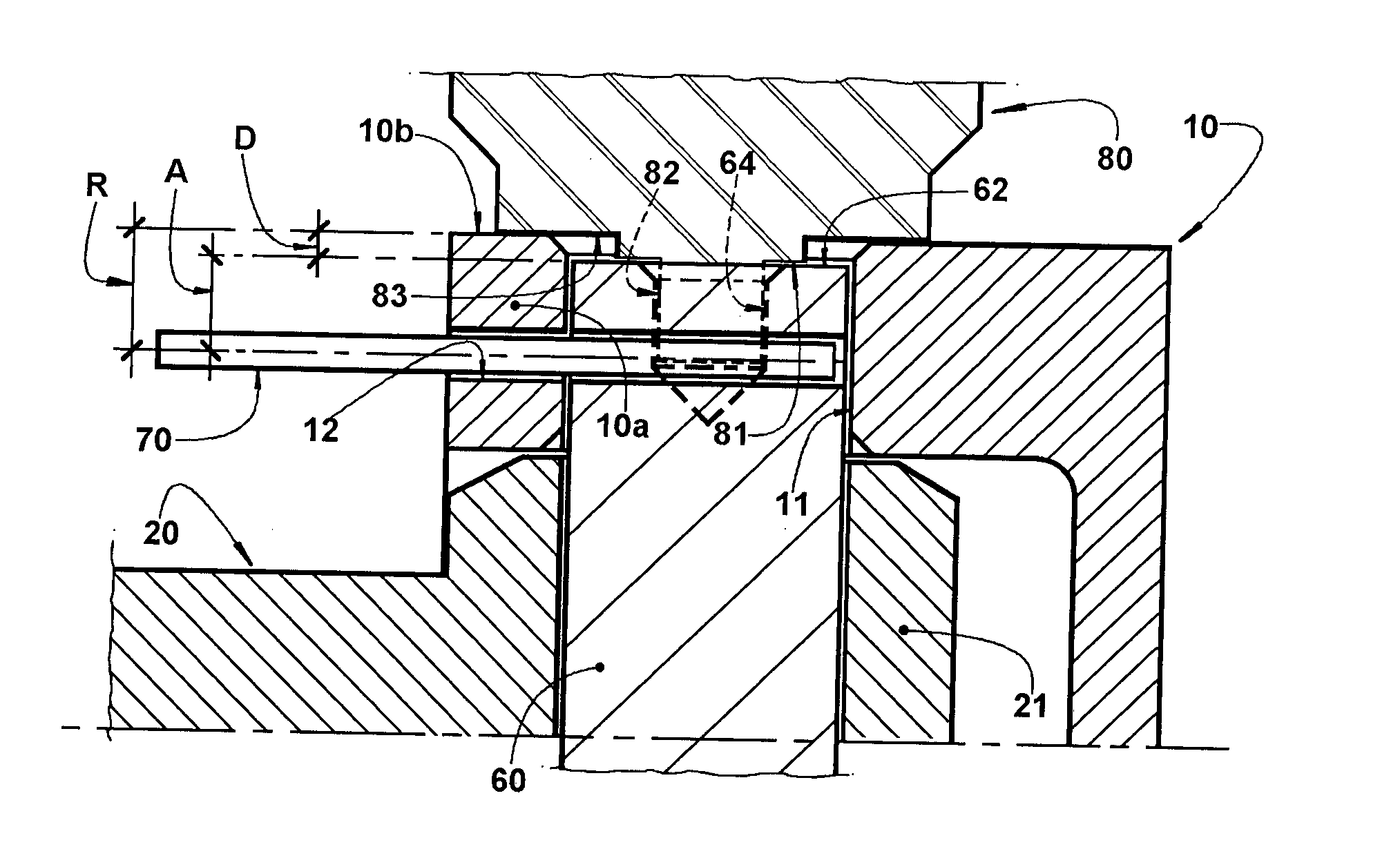
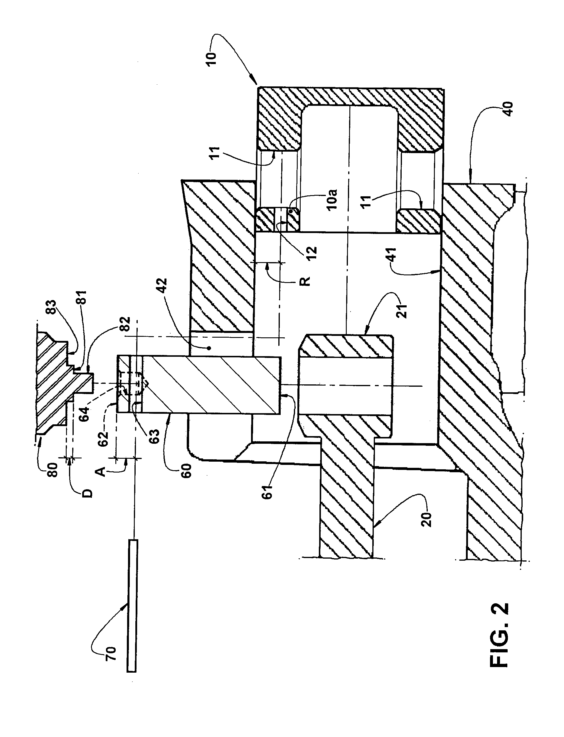
[0065]In the construction in which the recess 64b is eccentric in relation to the center of the contour of the second end of the wrist pin 60 and presents a circular contour, the tool 80 can present an end 81, to be seated against the second end 62 of the wrist pin 60 and incorporating a small axial projection 82, which can take the form of an eccentric pin, to be fitted in the recess 64b. The angular rotation of the tool 80 will produce the angular displacement of the wrist pin 60, so that the axis of its diametrical hole 63 occupies a direction coaxial to that of the axis of the eccentric ...


PUM


Abstract

The arrangement is applied to a compressor which comprises: a crankcase, carrying a cylinder provided with a lateral slot and in which is housed a piston provided with two radial holes and with an eccentric axial hole; a connecting rod connected to a crankshaft driven by an electric motor and having a smaller eye mounted in the piston; and a wrist pin having a first end turned to the bearing hub of the crankcase, a second end turned to the lateral slot of the cylinder and a diametrical hole, adjacent to the second end in which is provided an engaging means, for the axial and rotational coupling of a tool for mounting and indexing the wrist pin, in the interior of the piston, in a position in which the diametrical hole is axially aligned with the eccentric axial hole, so as to allow an elastic pin to be introduced in said diametrical hole and in said eccentric axial hole.

Description

FIELD OF THE INVENTION[0001]The present invention refers to a mounting arrangement for providing the coupling of a piston to the smaller. eye of a connecting rod which has a larger eye mounted to a crankshaft of a refrigeration compressor, of the reciprocating type, and comprising a crankcase, suspended in the interior of a shell and carrying a bearing hub and a cylinder, in the interior of which the piston is displaced by the connecting rod, in a reciprocating movement, upon the driving of the crankshaft by an electric motor carried by the crankcase.PRIOR ART[0002]It has been continuous the search for solutions aiming to increase the energy efficiency of reciprocating compressors used in small household and commercial refrigeration systems. One of the ways to obtain increased energy efficiency is by reducing the mechanical losses of the movable components, such as the one produced by the relative movement between the surfaces of a tribological pair. Said mechanical losses refer to ...

Claims


Application Information

Patent Timeline
Patent Type & Authority Applications(United States)
IPC IPC(8): F04B39/00
CPCF04B39/0005F04B39/0022F04B39/14F04B53/14F04B53/144F04B53/147F04B53/22F05C2251/02F16J1/18
Inventor SILVA, FABIANO DOMINGOSMANKE, ADILSON LUIZLONGO, GELSON
Owner EMBRACO IND DE COMPRESSORES E SOLUCOES EM REFRIGERACAO LTDA
Why Eureka
Try Eureka