Low-pressure egr control during compressor bypass valve operation

a compressor bypass valve and low-pressure technology, applied in the direction of electric control, machines/engines, mechanical equipment, etc., can solve the problems of engine performance degrading, reduce compressor surge, reduce over-dilution of intake charge, and increase egr

Active Publication Date: 2014-07-24
FORD GLOBAL TECH LLC
View PDF12 Cites 15 Cited by
  • Summary
  • Abstract
  • Description
  • Claims
  • Application Information

AI Technical Summary

Benefits of technology

[0004]The inventors herein have recognized the above issue and have devised various approaches to at least partially address it. In one example approach, LP EGR may be reduced upon opening of a CBV (e.g., opening of a CBV during tip out to reduce compressor surge). In this way, over-dilution of the intake charge may be reduced by recirculating less exhaust, or even no exhaust, to the intake passage during conditions where an air / EGR mixture is already flowing from downstream of the compressor to upstream of the compressor by way of the open CBV. Then, after closing of the CBV (e.g., closing of the CBV after a compressor surge risk estimate has fallen below a threshold), it may be determined whether intake air dilution has decreased below a threshold based on measurements taken by an intake oxygen sensor arranged downstream of the compressor. If so, depending on the threshold, little or no EGR may be present in the intake air, and thus EGR may be increased (e.g., to achieve a desired intake air dilution) without the risk of over-dilution of the intake charge (which may undesirably degrade engine performance). As a further advantage of this approach, undesirable EGR backflow may be reduced during compressor surge conditions due to the reduction in opening of the EGR valve.

Problems solved by technology

Therefore, if no action is taken to address this issue, the desired intake air dilution may not be achieved, and engine performance may be degraded.

Method used


Image

  • Low-pressure egr control during compressor bypass valve operation
  • Low-pressure egr control during compressor bypass valve operation
  • Low-pressure egr control during compressor bypass valve operation

Examples


Embodiment Construction

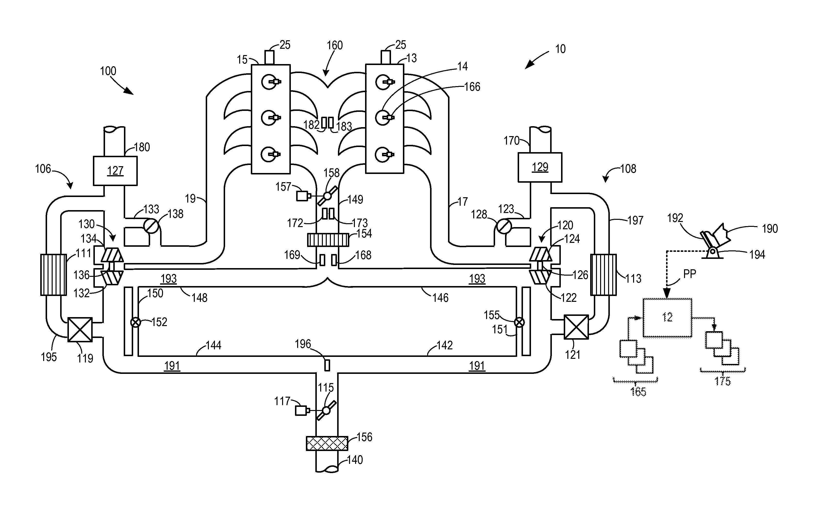
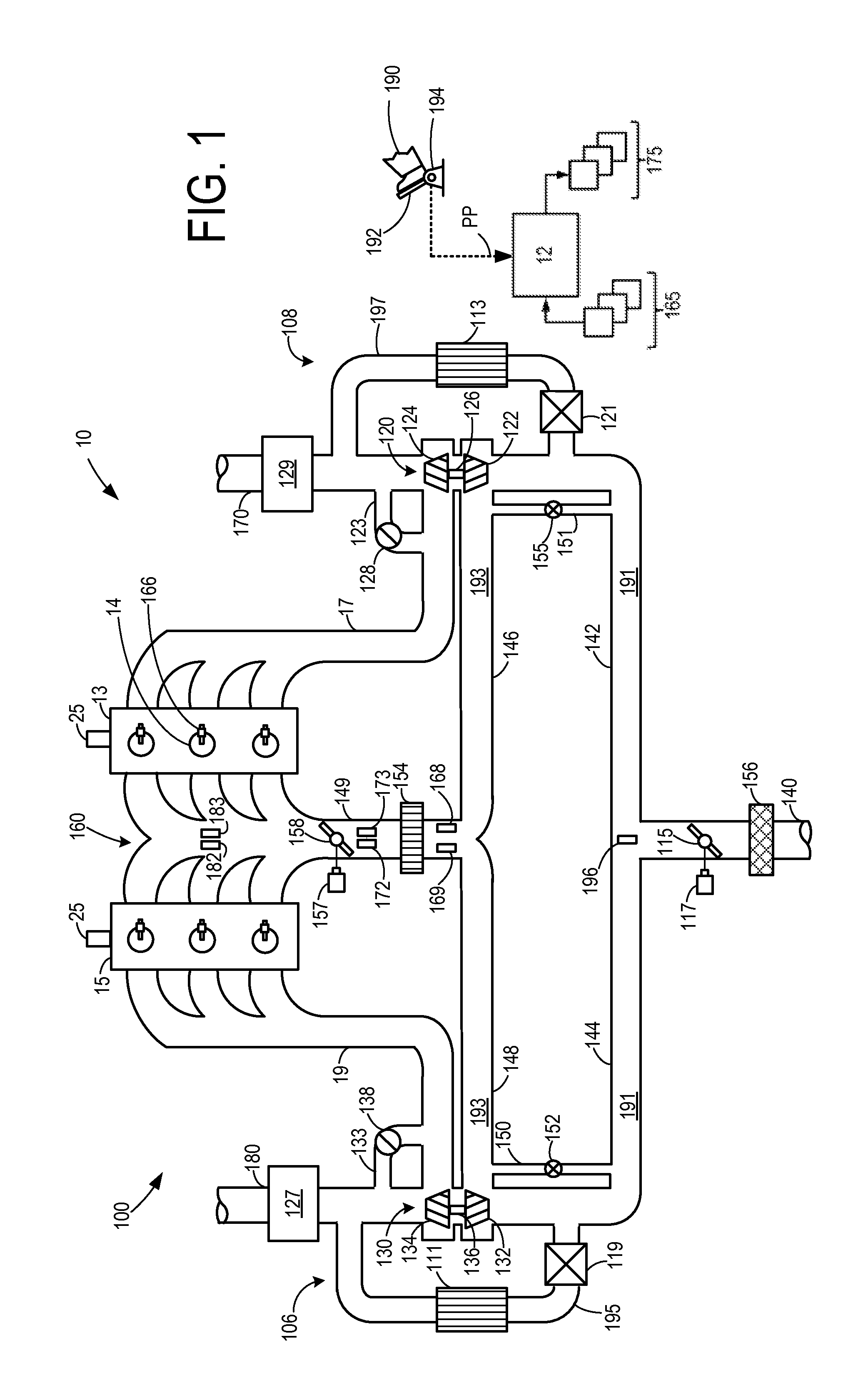
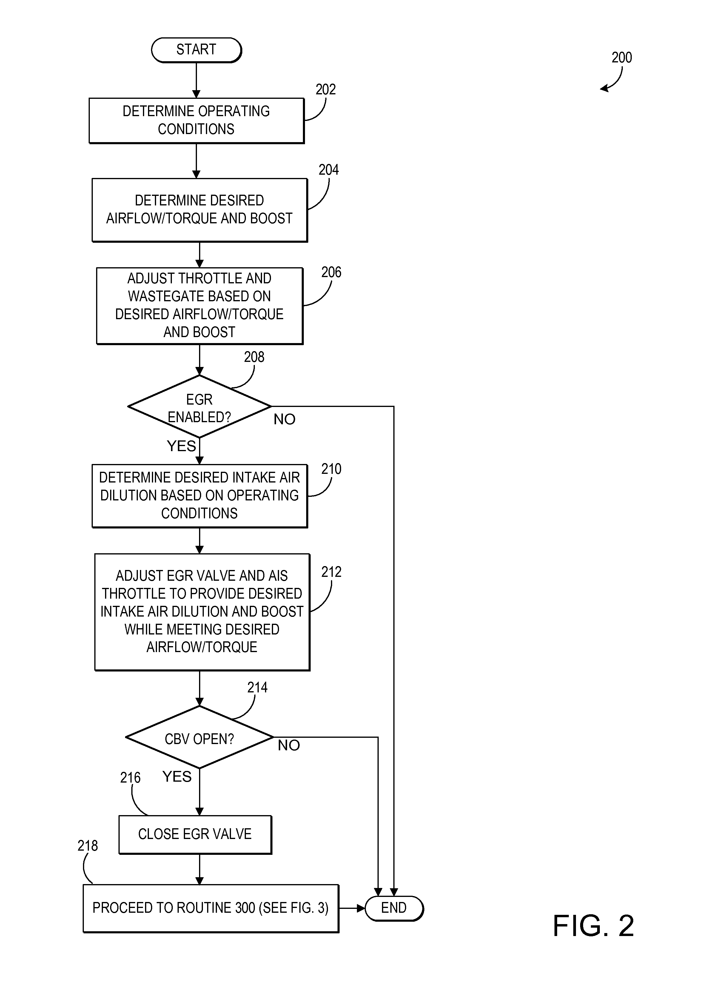
[0010]The following description relates to controlling LP EGR during operation of a CBV in an internal combustion engine. As shown in the example embodiment of FIG. 1, an engine system may include two branches, each equipped with a turbocharger and EGR system. An intake oxygen sensor arranged downstream of the compressors may measure intake air dilution, which may serve as a basis for adjustment of the CBV(s) as well as EGR as detailed with regard to the routines of FIGS. 2 and 3. For example, as shown in FIGS. 2 and 3, upon opening of the CBV, the EGR valve may be closed to avoid over-dilution of the intake charge. As shown in the timing diagrams of FIG. 4, once the CBV is closed (e.g., due to a compressor surge risk estimate falling below a threshold), and once the measured intake air dilution reflects that the intake system contains little or no EGR, EGR may be increased as needed to achieve a desired intake air dilution without risking over-dilution of the intake charge.

[0011]FI...


PUM


Abstract

A turbocharged engine system including a low-pressure exhaust gas recirculation (EGR) system and an intake oxygen sensor is described, along with methods for its operation. The system includes a compressor bypass valve arranged in a passage bypassing a turbocharger compressor, and an EGR valve arranged in an EGR system which may be adjusted to adjust an amount of exhaust gas recirculated to the engine intake. In one example method, over-dilution of an engine intake charge may be reduced by reducing EGR upon opening of the compressor bypass valve, and then increasing the EGR only after measurements from an intake oxygen sensor indicate that intake air dilution has decreased below a threshold.

Description

TECHNICAL FIELD[0001]The present application relates generally to controlling low-pressure exhaust gas recirculation during operation of a compressor bypass valve in an internal combustion engine.BACKGROUND AND SUMMARY[0002]Engine systems may utilize recirculation of exhaust gas from an engine exhaust system to an engine intake system, a process referred to as exhaust gas recirculation (EGR), to reduce regulated emissions. For example, a turbocharged engine system may include a low-pressure (LP) EGR system which recirculates exhaust gas from the exhaust system to the intake passage upstream of a turbocharger compressor. Accordingly, exhaust gas may be recirculated into a low-pressure air induction system (LP AIS) upstream of the compressor, resulting in a compressed mixture of fresh intake air and EGR downstream of the compressor. An EGR valve may be controlled to achieve a desired intake air dilution, the desired intake air dilution based on engine operating conditions.[0003]Howeve...

Claims


Application Information

Patent Timeline
Patent Type & Authority Applications(United States)
IPC IPC(8): F02B47/08
CPCF02B47/08F02B37/16F02B2037/125F02D41/0007F02D41/005F02D41/144F02M25/07F02M25/0709Y02T10/121Y02T10/144F02M26/06Y02T10/12Y02T10/40
Inventor HILDITCH, JAMES ALFREDSURNILLA, GOPICHANDRASTYLES, DANIEL JOSEPH
Owner FORD GLOBAL TECH LLC
Why Eureka
Try Eureka