Compressed Natural Gas Storage and Dispensing System

a compressed natural gas and storage technology, applied in the direction of liquid transfer devices, container discharging methods, liquid handling, etc., can solve the problems of fuel demand exceeding the supply available, gas pressure and volume of these pipelines is insufficient to support fast filling, and large disparity in volume, so as to achieve low flow rate and low horse power compressors

Active Publication Date: 2014-07-24
HOLYSTONE USA INC
View PDF7 Cites 34 Cited by
  • Summary
  • Abstract
  • Description
  • Claims
  • Application Information

AI Technical Summary

Benefits of technology

[0005]In various embodiments, a CNG fast-fill receiving, storing and dispensing fuel island is provided comprising preferably at least two banks or sets of tanks—a bank of “bulk storage tanks” and a bank of “dispensing storage tanks”. The bulk storage tanks are connected to the natural gas utility pipeline and are refilled to capacity throughout the course of the day via open and continuous access to the pipeline, the bulk storage tanks being refilled at the relatively low flow rate produced by pipeline pressure via compressors that raise the pressure to 5000 psi for example. The dispensing storage tanks receive the gas from the bulk storage tanks as needed as a result of the fuel being dispensed from the dispensing tanks to the CNG dispensers and into the motor vehicles. The depletion is measured in pressure, such that when the dispensing storage tanks go below a designated minimum pressure, typically 3600 psi, valves that connect the two banks of tanks through a manifold system of pipes automatically transfer the gas stored in the bulk storage tanks into the dispensing storage tanks. To insure constant high pressure within the dispensing tanks, the gas from the bulk storage tanks is recompressed up to 5000 psi for example prior to delivery to the dispensing storage tanks. Because a relatively low flow rate for filling the bulk storage tanks is acceptable, relatively low horse power compressors may be utilized. Likewise, relatively low horsepower compressors may be utilized to recompress the gas delivered from the bulk storage tanks, since the gas will be at a pressure of greater than 3600 psi. This same design can also be employed to accommodate other CNG sources, such a tube trailer, or liquid natural gas (LNG), where the source of the natural gas is an LNG tanker instead of the municipal utility gas pipeline.
[0006]In an alternative description, the invention is a compressed natural gas storage and dispensing system adapted to deliver natural gas to motor vehicles, the system comprising: a plurality of bulk storage tanks in fluid communication with a natural gas supply source, said bulk storage tanks being type 4, 4/5 or 5 tanks composed of a resin composite material; at least one primary compressor drawing natural gas from said supply source, compressing the natural gas to a desired pressure, and delivering the natural gas to said bulk storage tanks, said at least one primary compressor being from 50-150 horsepower; a plurality of dispensing storage tanks in fluid communication with said bulk storage tanks and in fluid communication with fuel dispensers, said dispensing storage tanks being type 4, 4/5 or 5 tanks composed of a resin composite material, the number of said dispensing storage tanks being less than the number of said bulk storage tanks; at least one secondary compressor receiving said natural gas from said bulk storage tanks, compressing the natural gas to a desired pressure, and delivering said natural gas to said dispensing storage tanks, said at least one secondary compressor being from 50-150 horsepower; wherein when the pressure within said dispensing storage tanks falls below a predetermined minimum pressure, natural gas is delivered from said bulk storage tanks to said dispensing storage tanks, and wherein when

Problems solved by technology

However, the gas pressure and volume from these pipelines is insufficient to support fast-fill, i.e., CNG-on-demand, islands.
Inconsistent demands for natural gas throughout the day by neighboring customers sharing the pipeline create widely disparate volume and pressures that are detrimental for optimum operation of open-traffic fast-fill

Method used


Image

  • Compressed Natural Gas Storage and Dispensing System
  • Compressed Natural Gas Storage and Dispensing System

Examples


Embodiment Construction

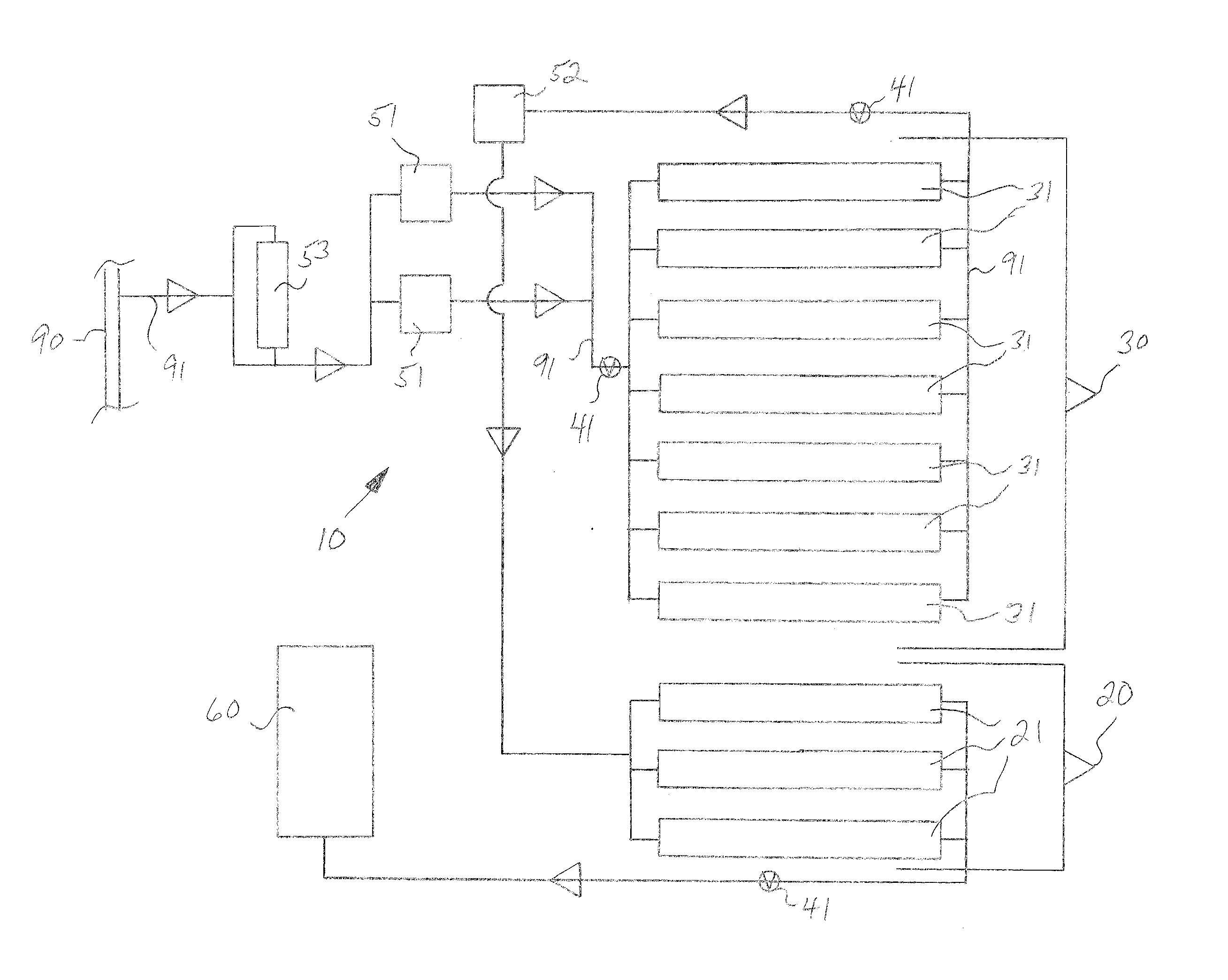
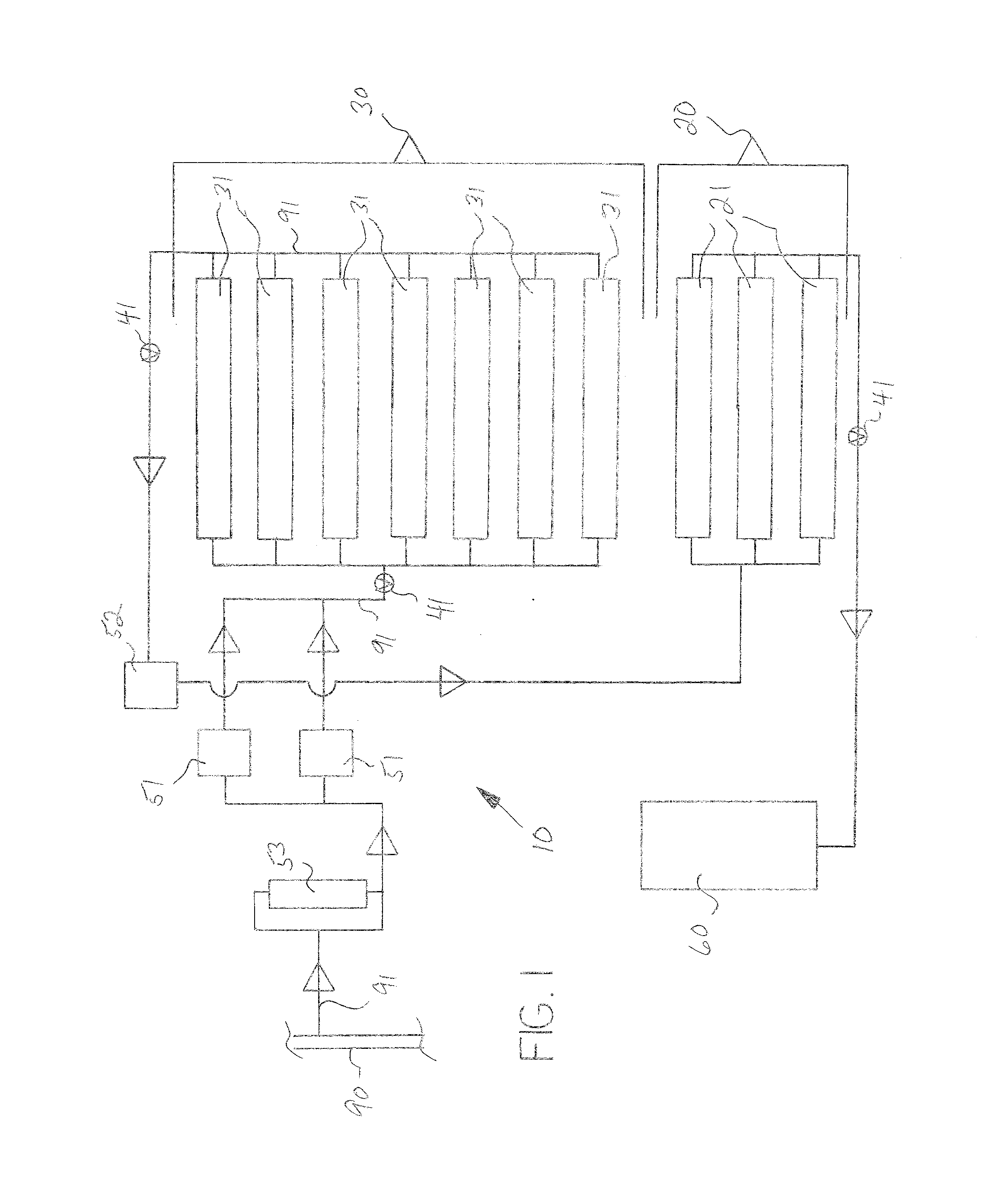
[0009]With reference to any drawings and charts, embodiments of the invention will now be described in enabling detail. In general, an exemplary embodiment of the method and system is a CNG receiving, storing and dispensing fast-fill fuel island system 10 adapted to receive vehicular traffic acquiring CNG on demand, the system 10 comprising preferably at least two banks or sets of CNG storage tanks—a bank 20 of dispensing storage tanks 21 and a bank 30 of bulk storage tanks 31. The bulk storage tanks 31 are connected to the natural gas utility pipeline 90 and are continuously being filled to capacity throughout the course of the day as needed via open and continuous conduits 91 communicating with the pipeline 90, with the gas being suctioned from the pipeline 90 and compressed by primary compressors 51 to the desired pressure (5000 psi for example). The dispensing storage tanks 21 receive the gas from the bulk storage tanks 31 as needed as a result of the fuel being dispensed throug...


PUM

PropertyMeasurementUnit
Pressureaaaaaaaaaa
Pressureaaaaaaaaaa
Poweraaaaaaaaaa

Abstract

A compressed natural gas storage and dispensing system having bulk storage tanks in fluid communication with a natural gas supply source; a primary compressor delivering the natural gas to the bulk storage tanks; dispensing storage tanks in fluid communication with the bulk storage tanks and in fluid communication with fuel dispensers; a secondary compressor delivering the natural gas to the dispensing storage tanks from the bulk storage tanks; wherein when the pressure within the dispensing storage tanks falls below a predetermined minimum pressure, natural gas is delivered from the bulk storage tanks to the dispensing storage tanks, and wherein when the pressure in the bulk storage tanks falls below a predetermined minimum pressure, natural gas is delivered from the supply source to the bulk storage tanks.

Description

[0001]This application claims the benefit of United States Provisional Patent Application Ser. No. 61 / 849,207, the disclosure of which is incorporated herein by reference.BACKGROUND OF THE INVENTION[0002]This invention relates generally to the field of receiving, storing and dispensing compressed natural gas, and more particularly relates to systems and methods for receiving natural gas from pipelines or delivery vehicles, compressing and storing the natural gas, and dispensing the natural gas into vehicles from fuel islands.[0003]Using compressed natural gas (“CNG”) for motor vehicle fuel is relatively new in the U.S. It is anticipated that most CNG fuel islands, designed and structured to dispense CNG to individual vehicles in the manner of standard gas stations, will obtain natural gas by direct connection to utility pipelines, as provided by municipal infrastructure. However, the gas pressure and volume from these pipelines is insufficient to support fast-fill, i.e., CNG-on-dema...

Claims


Application Information

Patent Timeline
IPC IPC(8): F17C5/06
CPCF17C5/06F17C5/007F17C7/00F17C9/00F17C9/02F17C2203/0663F17C2205/0138F17C2205/0142F17C2205/0326F17C2221/033F17C2223/0123F17C2223/0161F17C2223/033F17C2223/036F17C2225/0123F17C2225/036F17C2227/0157F17C2227/0185F17C2227/0393F17C2250/043F17C2250/0439F17C2250/0452F17C2260/025F17C2260/056F17C2265/015F17C2265/065F17C2270/0139F17C2270/07
Inventor BARKER, R. KEITH
Owner HOLYSTONE USA INC
Why Eureka
Try Eureka