Power conversion device

a power conversion device and power supply technology, applied in the direction of motor/generator/converter stopper, dynamo-electric converter control, control system, etc., can solve the problems of not only the power conversion device main body b>2/b>, but also the input capacitor b>6/b> and the like, and the difficulty in counteracting a direct current power supply voltage rise, so as to effectively protect the power conversion device main body, the effect of b>

Active Publication Date: 2014-07-24
FUJI ELECTRIC CO LTD
View PDF9 Cites 10 Cited by
  • Summary
  • Abstract
  • Description
  • Claims
  • Application Information

AI Technical Summary

Benefits of technology

[0015]As such, a rise in the direct current power supply voltage caused by regenerative power is effectively suppressed, and it is possible to protect the power conversion device main body from overvoltage, thus forestalling damage thereto. Moreover, it is possible to effectively protect the power conversion device main body from regenerative power with a simple configuration in which, for example, the Zener diode is installed between the positive electrode line to which the power supply voltage is applied and the control terminal of the semiconductor switch circuit, to which there are considerable practical advantages.

Problems solved by technology

Because of this, it is difficult to counteract a rise in the direct current power supply voltage Vin due to regenerative power in the brake circuit 3.
As a result, there is concern about not only the power conversion device main body 2, but also the input capacitor 6 and the like, being damaged by overvoltage.
Specifically, the brake circuit includes, for example, a semiconductor switch circuit that, when conductive, forms a bypass current path with respect to the power conversion device main body, thus consuming excess power.

Method used


Image

  • Power conversion device
  • Power conversion device
  • Power conversion device

Examples


Embodiment Construction

[0019]Hereafter, referring to the drawings, a description will be given of a power conversion device according to embodiments of the invention.

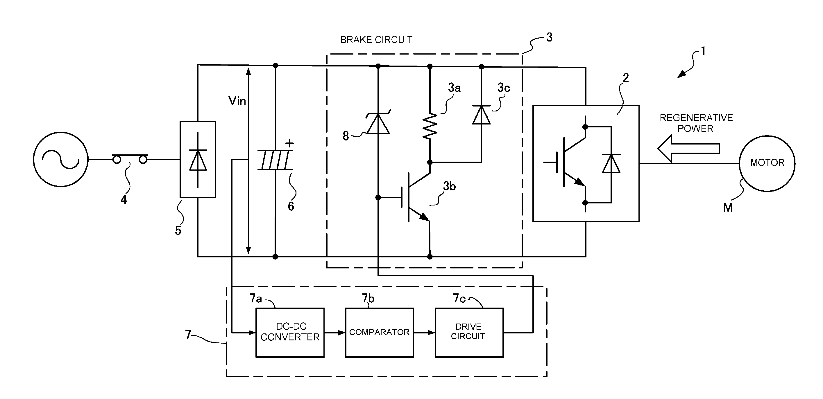
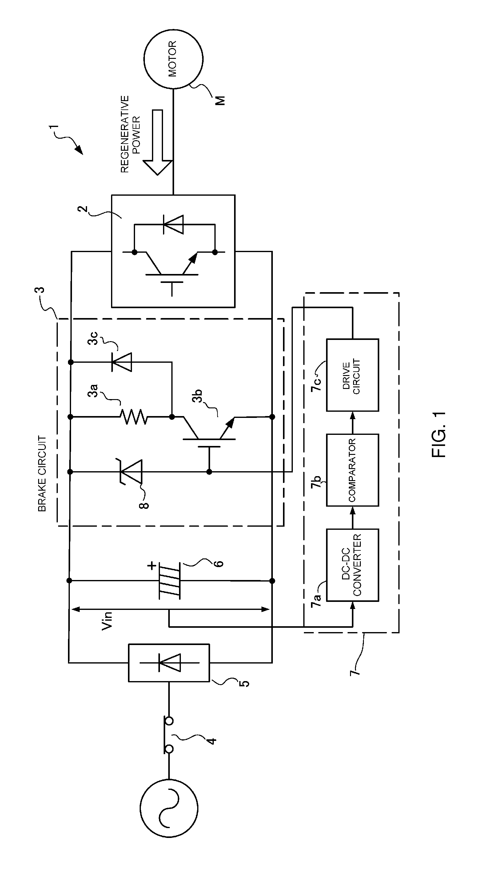
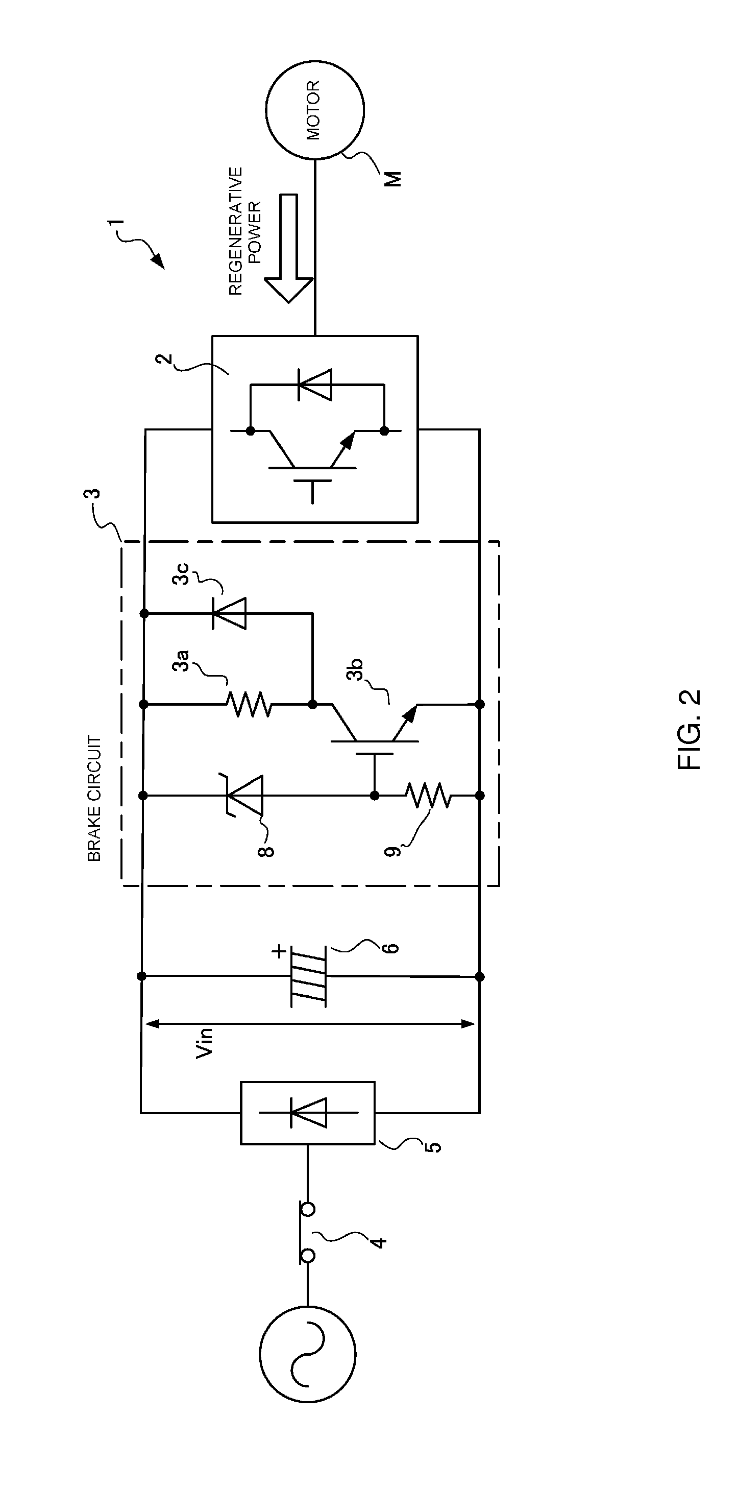
[0020]A power conversion device 1 according to the invention is basically configured to include a power conversion device main body (inverter circuit) 2 and a brake circuit 3 connected in parallel to the power conversion device main body 2, in the same way as a heretofore known power conversion device shown in FIG. 3. Consequently, the same reference signs are given to portions the same as those of the heretofore known device, and a description thereof will be omitted.

[0021]The power conversion device 1 according to this embodiment is characterized in that a Zener diode 8 is installed between a positive electrode line of a direct current power supply voltage Vin and the gate of a semiconductor switch 3b (the control terminal of a semiconductor switching circuit) in the brake circuit 3, as shown in a main portion schematic configuration diagra...


PUM


Abstract

A power conversion device for driving a load, including a power conversion device main body configured to receive an input of a power supply voltage and to drive the load, and a brake circuit configured to protect the power conversion device main body from overvoltage applied thereto. The brake circuit includes a Zener diode that becomes conductive when the voltage applied to the power conversion device main body exceeds a predetermined value, to thereby suppress the voltage.

Description

CROSS REFERENCE TO RELATED APPLICATION[0001]This application claims the priority of a corresponding Japanese patent application, Serial No. JP PA 2013-007323, filed Jan. 18, 2013, the entire content of which is hereby incorporated by reference.BACKGROUND OF THE INVENTION[0002]1. Field of the Invention The present invention relates to a power conversion device including a protection function with respect to regenerative power from a load.[0003]2. Description of the Background Art[0004]A large number of power conversion devices, typified by inverter devices, are used as drive devices that drive a load such as a motor. This type of power conversion device, in outline, is configured so as to switch an input power supply voltage, which is a rectified commercial power supply, via a semiconductor switching element such as an IGBT (insulated-gate bipolar transistor) or MOSFET (metal-oxide-semiconductor field-effect transistor), thus generating power, for example a three-phase alternating cu...

Claims


Application Information

Patent Timeline
Patent Type & Authority Applications(United States)
IPC IPC(8): H02P3/22
CPCH02P3/22H02P29/0241H02P29/024
Inventor OGAWA, SHOGO
Owner FUJI ELECTRIC CO LTD
Why Eureka
Try Eureka