

Methods of manufacturing turbomachines blades with shaped channels by additive manufacturing, turbomachine blades and turbomachines
a technology of additive manufacturing and turbomachines, which is applied in the direction of turbines, marine propulsion, vessels, etc., can solve problems such as damage to the rotor blades, and achieve the effect of low production cost and high precision
- Summary
- Abstract
- Description
- Claims
- Application Information
AI Technical Summary
Benefits of technology
Problems solved by technology
Method used
Image

Examples
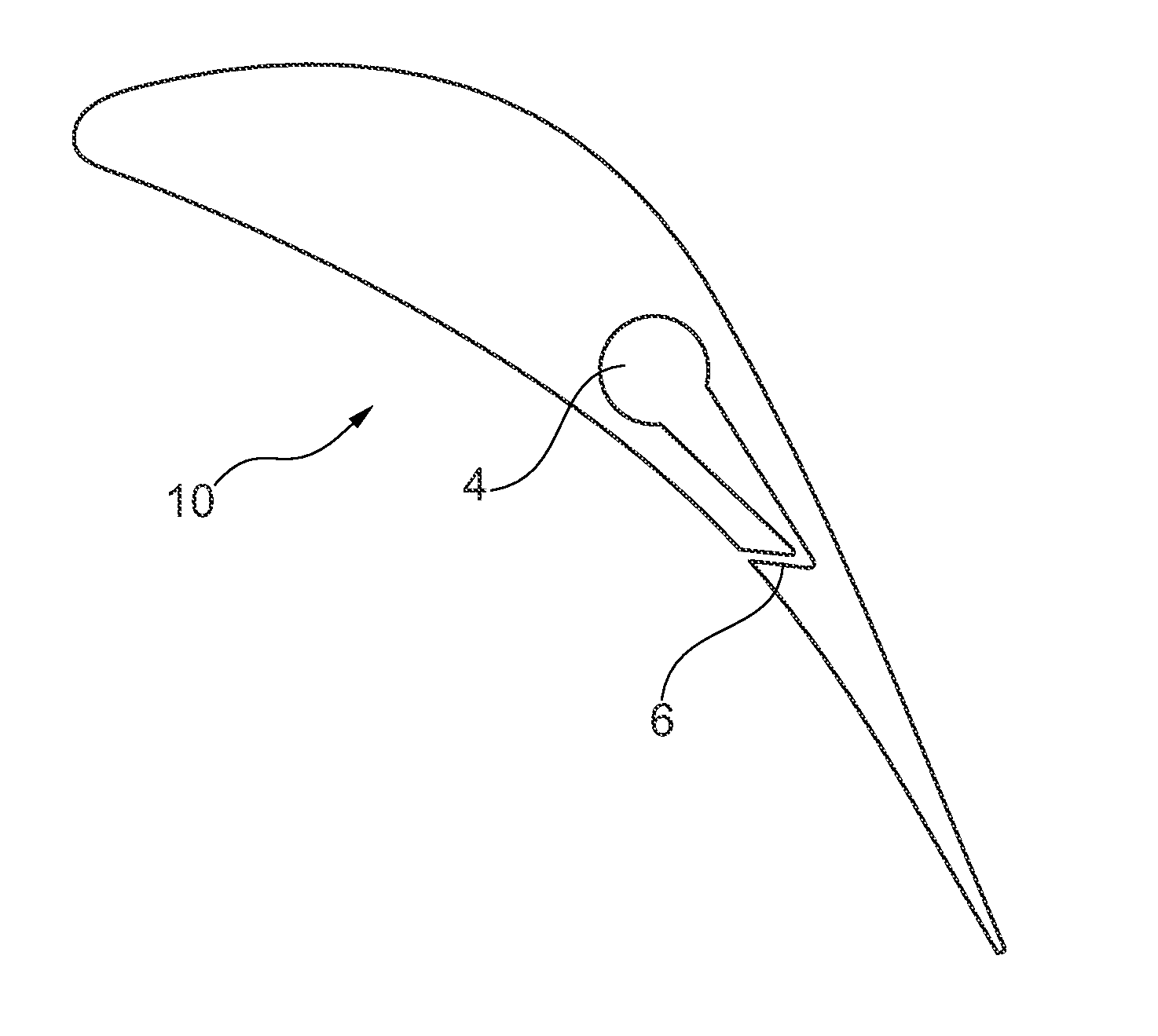
embodiment 10
[0045]In the embodiment 10 of FIG. 1, there is only one internal cavity 4; channels 6 are inclined and lead to the laterally displaced internal cavity 4; the cavity 4 is use to suck condensation and the channels 6 are inclined so to facilitate the movement of the fluid from the external surface of the airfoil portion 1, along the channels 6 and into the internal cavity 4 (considering also the fluid flow around the airfoil portion during operation of the machine). In this embodiment, the channels 6 correspond to a plurality of long slots arranged in two rows (as shown in FIG. 3 on the right) and correspondingly one short conduit is shown in FIG. 1. The shape of the chamber 4 and the arrangement of the channels 6 allow to locate the sucking area very close to the trailing edge of the airfoil portion 1 of the blade 10.
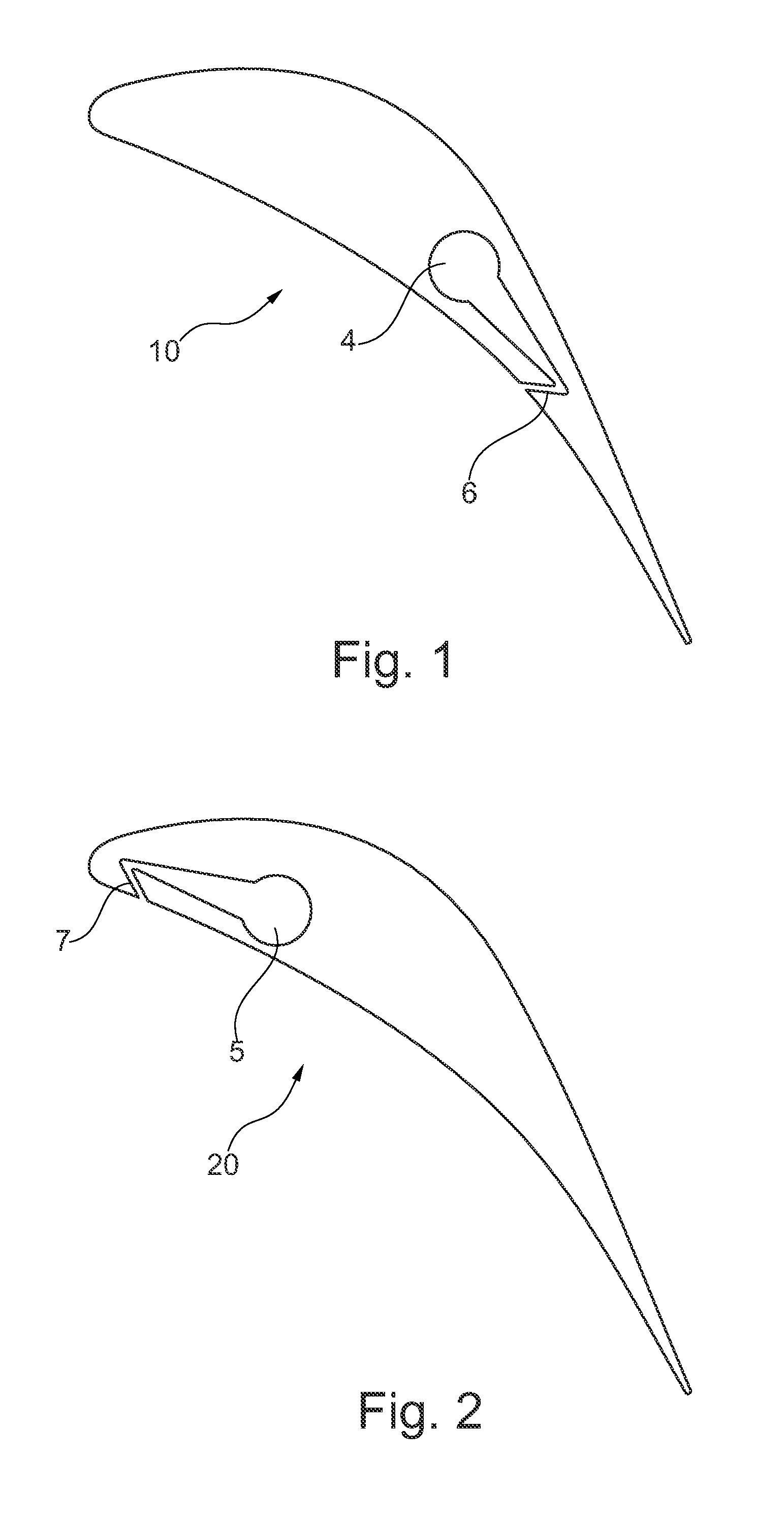
embodiment 20
[0046]In the embodiment 20 of FIG. 2, there is only one internal cavity 5; the channels 7 are inclined and lead to the laterally displaced internal cavity 5; the cavity 5 is used to eject a fluid (typically a hot fluid) and the channels 7 are inclined so to facilitate the movement of the fluid from the internal cavity 5, along the channels 7, to the external surface of the airfoil portion 1 (considering also the fluid flow around the airfoil portion during operation of the machine). In this embodiment, the channels 7 correspond to a plurality of short slots arranged in one rows (as shown in FIG. 3 on the left) and correspondingly one short conduit is shown in FIG. 2. The shape of the chamber 5 and the arrangement of the channels 7 allow to locate the ejection area very close to the leading edge of the airfoil portion 1 of the blade 20.
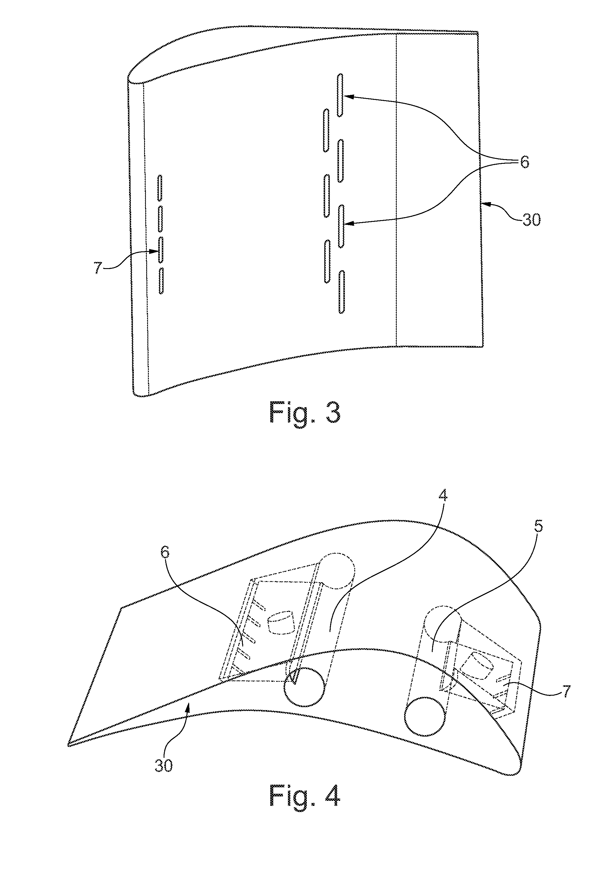
embodiment 30
[0047]In the embodiment 30 of FIG. 3 and FIG. 4, the technical features of both embodiments 10 and 20 of FIG. 1 and FIG. 2 are combined, i.e. there is sucking of a fluid into the airfoil portion of the blade and there is ejection of fluid out of the airfoil portion of the blade; both sucking and ejection take place on the pressure side of the airfoil; on the contrary, in the embodiment of FIG. 5, sucking takes place on the pressure side while ejection takes place on the suction side; it is two be noted that a variant of the embodiment of FIG. 5 may provide to have sucking from both sides (i.e. two corresponding sets of channels) and ejection on both sides (i.e. two corresponding sets of channels).
[0048]The channels may lie in a plane perpendicular to the axis of the blade.
[0049]Alternatively, the channel may extend across a plurality of planes perpendicular to the axis of the blade; this is the case of channels 6 and 7 in FIG. 4.
[0050]Depending on the function of the internal cavity...
PUM
| Property | Measurement | Unit |
|---|---|---|
| length | aaaaa | aaaaa |
| pressure | aaaaa | aaaaa |
| rotation speed | aaaaa | aaaaa |
Abstract
Description
Claims
Application Information