Rim Anchoring Systems for Flexible Surgical Implants for Replacing Cartilage

a flexible surgical implant and rim anchoring technology, applied in the field of surgical implants, can solve the problems of nitinol devices that cannot make self-directed transitions into shorter or longer lengths, other shapes, and other different shapes, and achieve the effect of greater strength and stability of implants

Active Publication Date: 2014-07-24
FORMAE
View PDF4 Cites 0 Cited by
  • Summary
  • Abstract
  • Description
  • Claims
  • Application Information

AI Technical Summary

Benefits of technology

[0035]Improved designs are disclosed for flexible implants that will be used to surgically replace hyaline or meniscal cartilage, in synovial joints. In one preferred embodiment, a hydrophilic polymer, molded generally in the shape of a damaged cartilage segment that needs to be replaced, will have an enlarged peripheral rim that is substantially thicker than the interior portions of the implant. That enlarged peripheral rim will be designed to fit, in an accommodating manner, into a “groove” that will be machined (with the help of templates, computerized tools, etc.) into the bone surface that will receive and support the implant. This will create an interlocking-type “fit” that will provide greater strength and stability for the implant, to allow it to resist shear forces even during a fall, accident, or other moment of “peak loading” or peak stress.
[0036]If desired, a “stabilizing ring”, which can be made of a shape-memory and / or super-elastic material (such as a “nitinol”-type alloy, if desired), or alternately from a braided or twisted multi-strand wire, cable, or similar component, can be embedded within the peripheral rim of the polymer component. This can allow the implant to be flexed into a cylindrical or other elongated, compressed, or other shape, for minimally-invasive insertion into a joint (such as via an arthroscopic insertion tube). After the implant has entered the joint, it will emerge from the insertion tube, or otherwise will be allowed or caused to return to its normal shape. This will enable the implant, with its enlarged outer rim containing a “stabilizing ring” component embedded within that rim, to perform a reinforcing and stabilizing role when the enlarged and reinforced flexible polymer rim of the implant settles into the bone groove.

Problems solved by technology

Accordingly, nitinol devices will not make self-directed transitions into shorter or longer lengths, or other different shapes, when chilled or heated.
However, a typical rubber band that has a substantial length will not attempt to return to a certain specific shape.
However, additional research by the Applicant has identified an important obstacle to such use of nitinol alloys, in implants that will remain in a patient's body for an extended period of time.
That obstacle involves a risk of corrosion, which is believed to arise primarily in areas where nickel atoms cluster together in “nickel-enriched” clusters or “pockets” that can have molecular structures and / or “lattice ratios” such as Ni3Ti.
As a result, during the manufacture of a nitinol component, if small pockets of material are formed that have nickel content greater than 50%, the nickel atoms in those pockets can be leached out, over a span of months or years, in ways that can lead to corrosion, cavities, and structural weakness.
Those types of long-term testing requirements could lead to severe problems and delays, especially if the main goal of such long-term clinical trials would be to ensure that a certain type of component material will not slowly corrode, over a span of a decade or more, in a mammalian joint.

Method used


Image

  • Rim Anchoring Systems for Flexible Surgical Implants for Replacing Cartilage
  • Rim Anchoring Systems for Flexible Surgical Implants for Replacing Cartilage
  • Rim Anchoring Systems for Flexible Surgical Implants for Replacing Cartilage

Examples


Embodiment Construction

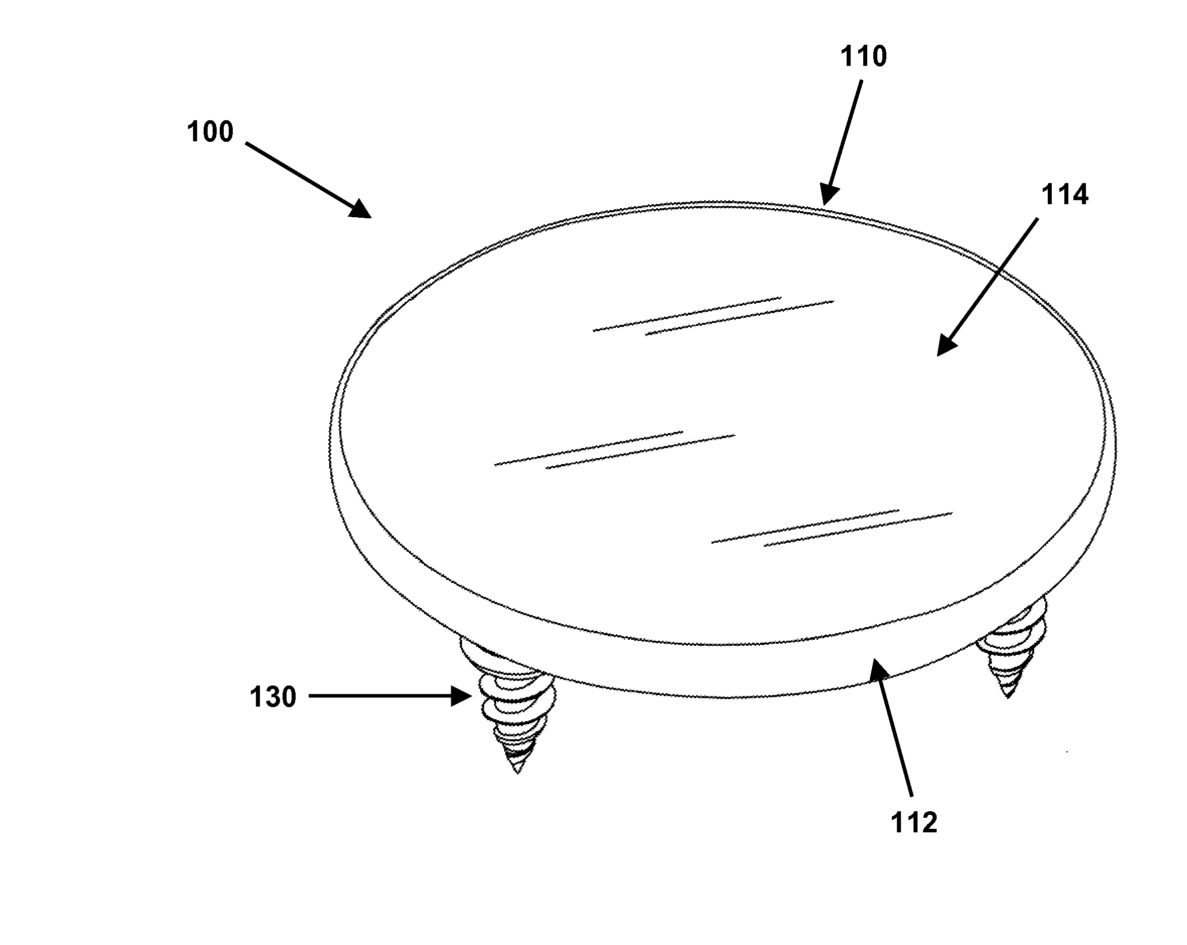
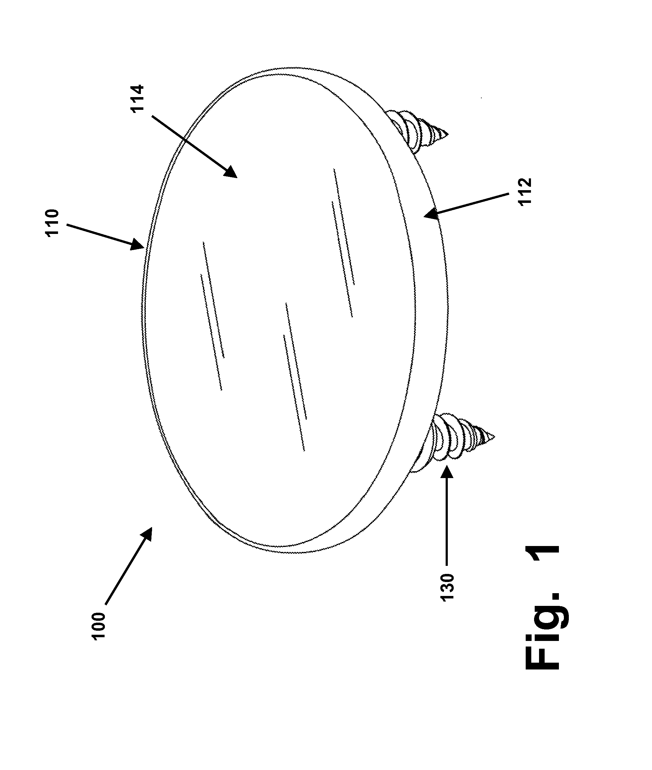
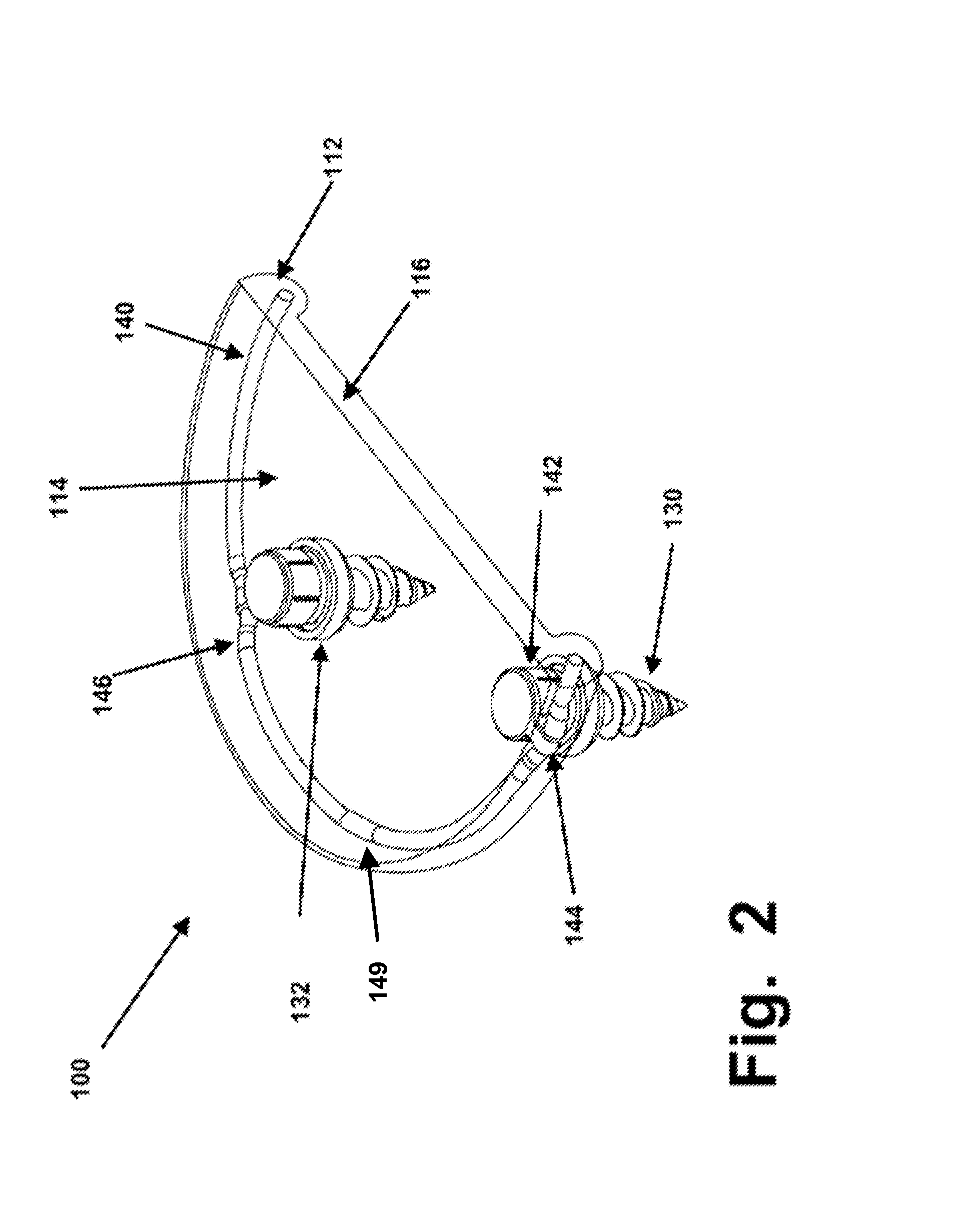
[0049]As briefly summarized above, a surgical implant 100, designed for replacing a relatively large segment of hyaline cartilage in a synovial joint such as a knee, shoulder, hip, etc.) is illustrated in FIGS. 1-3. Scaled-down implants with the same structures described herein, but with smaller diameters and thicknesses (and with only one or two anchoring screws, pins, or other components, which also can be smaller) also can be created for replacing hyaline cartilage in smaller joints, such as in thumbs, fingers, wrists, etc.

[0050]For simplicity of illustration, implant 100 is shown as having a generally round and flat shape. In actual use, any such implant designed for a large joint should have a molded and shaped articulating surface that will closely emulate the size and shape of the cartilage segment that is being replaced by the implant. The sizes and shapes of such cartilage surfaces (such as, within a knee joint, the medial and lateral femoral runners, the tibial plateau, an...


PUM


Abstract

Flexible cartilage-replacing implants are disclosed that use either or both of (1) enlarged peripheral rim components, and / or (2) elongated flexible reinforcing members that are embedded around the peripheral edge of an implant device. These types of anchoring devices, especially when used in combination, can provide flexible implants that can be implanted arthroscopically into synovial joints, for complete replacement of damaged cartilage segments.

Description

RELATED APPLICATION[0001]This application is a continuation-in-part of U.S. utility application Ser. No. 13 / 355,276, which in turn claimed priority, under 35 USC 119, based on provisional application 61 / 434,145, filed on Jan. 19, 2011.BACKGROUND OF THE INVENTION[0002]This invention is in the field of surgical implants, and relates to devices and methods for repairing hyaline or meniscal cartilage in joints such as knees, hips, fingers, shoulders, etc.[0003]In joints that are lubricated by synovial fluid, hyaline and meniscal cartilage segments provide smooth, slippery, lubricated (or lubricious) surfaces that enable bones to move and slide, relative to other bones. “Hyaline” cartilage refers to the types of cartilage segments that are affixed, in relatively thin layers, directly to bone surfaces (often called condyles). Background information on hyaline cartilage, and on surgical implants for replacing injured or diseased hyaline cartilage, is available from various sources, includi...

Claims


Application Information

Patent Timeline
Patent Type & Authority Applications(United States)
IPC IPC(8): A61F2/30A61F2/38
CPCA61F2/3872A61F2/30756A61F2/30767A61F2/3094A61F2/30965A61F2/32A61F2/389A61F2/40A61F2/4637A61F2002/2821A61F2002/30113A61F2002/30115A61F2002/302A61F2002/30225A61F2002/30299A61F2002/30354A61F2002/30459A61F2002/30461A61F2002/30495A61F2002/305A61F2002/30604A61F2002/30738A61F2002/3085A61F2002/30878A61F2002/30892A61F2002/4635A61F2210/0019A61F2220/0016A61F2220/0025A61F2220/0033A61F2220/0066A61F2220/0075A61F2230/0006A61F2230/0008A61F2230/0065A61F2230/0069A61F2230/0093A61F2002/30757
Inventor MANSMANN, KEVIN A.
Owner FORMAE
Why Eureka
Try Eureka