
Premixed compression self-ignition engine

a self-ignition engine and compressor technology, applied in the direction of positive displacement engines, connecting rods, shafts and bearings, etc., can solve the problems of limited usable load, difficult to ensure an output, limited operating range of such premixed compression self-ignition four-cycle engines, etc., to achieve high compression ratio, low nox emission, and high thermal efficiency

Inactive Publication Date: 2014-07-31
HONDA MOTOR CO LTD
View PDF11 Cites 4 Cited by
  • Summary
  • Abstract
  • Description
  • Claims
  • Application Information

AI Technical Summary

Benefits of technology

The present invention provides a premixed compression self-ignition engine that is compact but still capable of achieving high thermal efficiency and low NOx emission while ensuring a practical output. This is achieved by employing the trigonal link and the swing link which increases the piston stroke while preventing enlargement of the crankcase as much as possible, reducing heat loss and improving the thermal efficiency. Additionally, the engine includes a scavenging port, exhaust port, and exhaust valve, which enables two-cycle operation enabling uniflow scavenging and discharge, and as a result, large-amount internal EGR introduction into a combustion chamber, achieving premixed compression self-ignition combustion with low NO emission and a high thermal efficiency while ensuring a practical output without increasing the number of auxiliaries. The piston stroke / the cylinder bore diameter is ≧1, which reduces the issue of blow-by of an air-fuel mixture and ensures the required flow path area for scavenging, and a cylinder cone angle should be set appropriately to optimize the flow in the cylinder.

Problems solved by technology

However, it is known that an operating range of such premixed compression self-ignition four-cycle engines is limited because it is difficult to control combustion under practical conditions, and that an usable load is limited, making it difficult to ensure an output, because knocking occurs at high loads.

Method used


Image

  • Premixed compression self-ignition engine
  • Premixed compression self-ignition engine
  • Premixed compression self-ignition engine

Examples


first embodiment

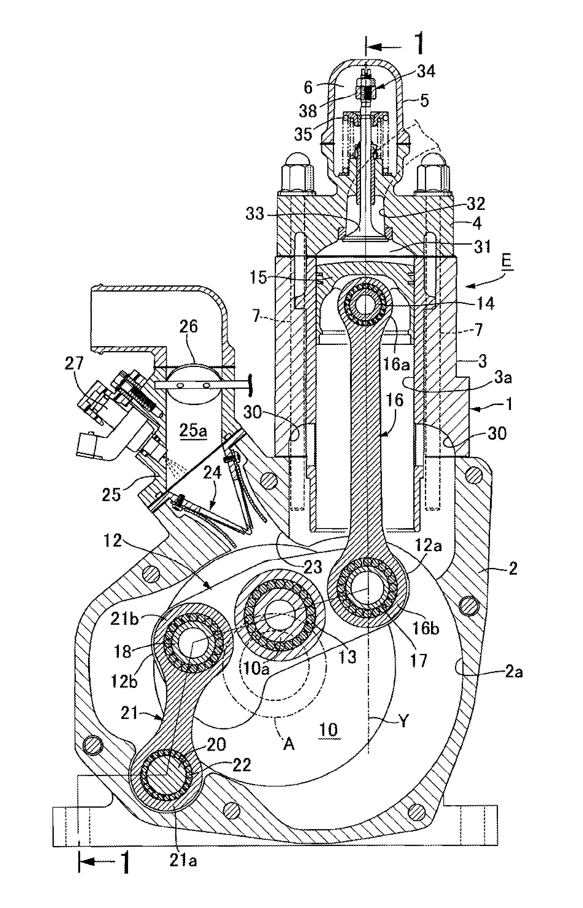
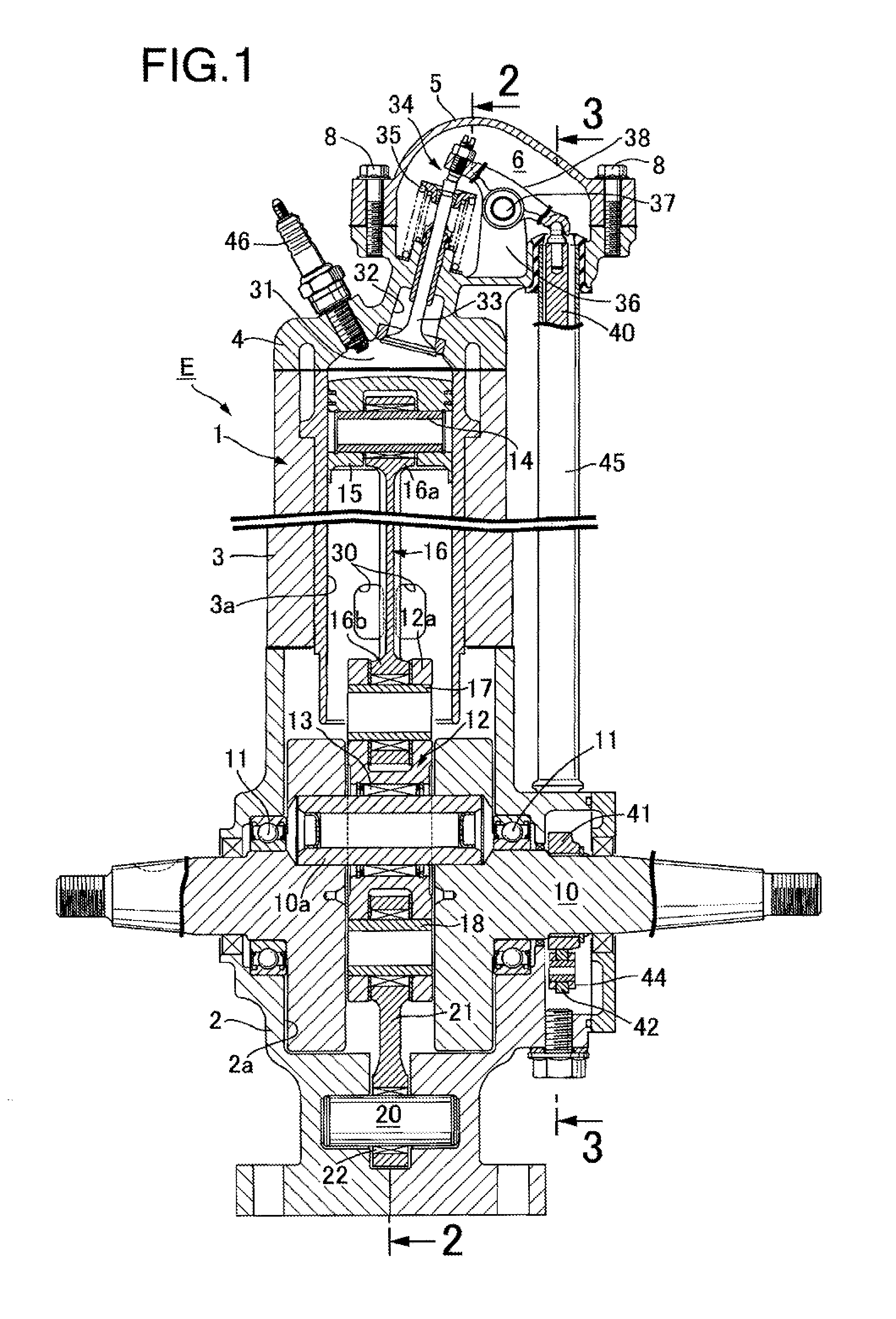
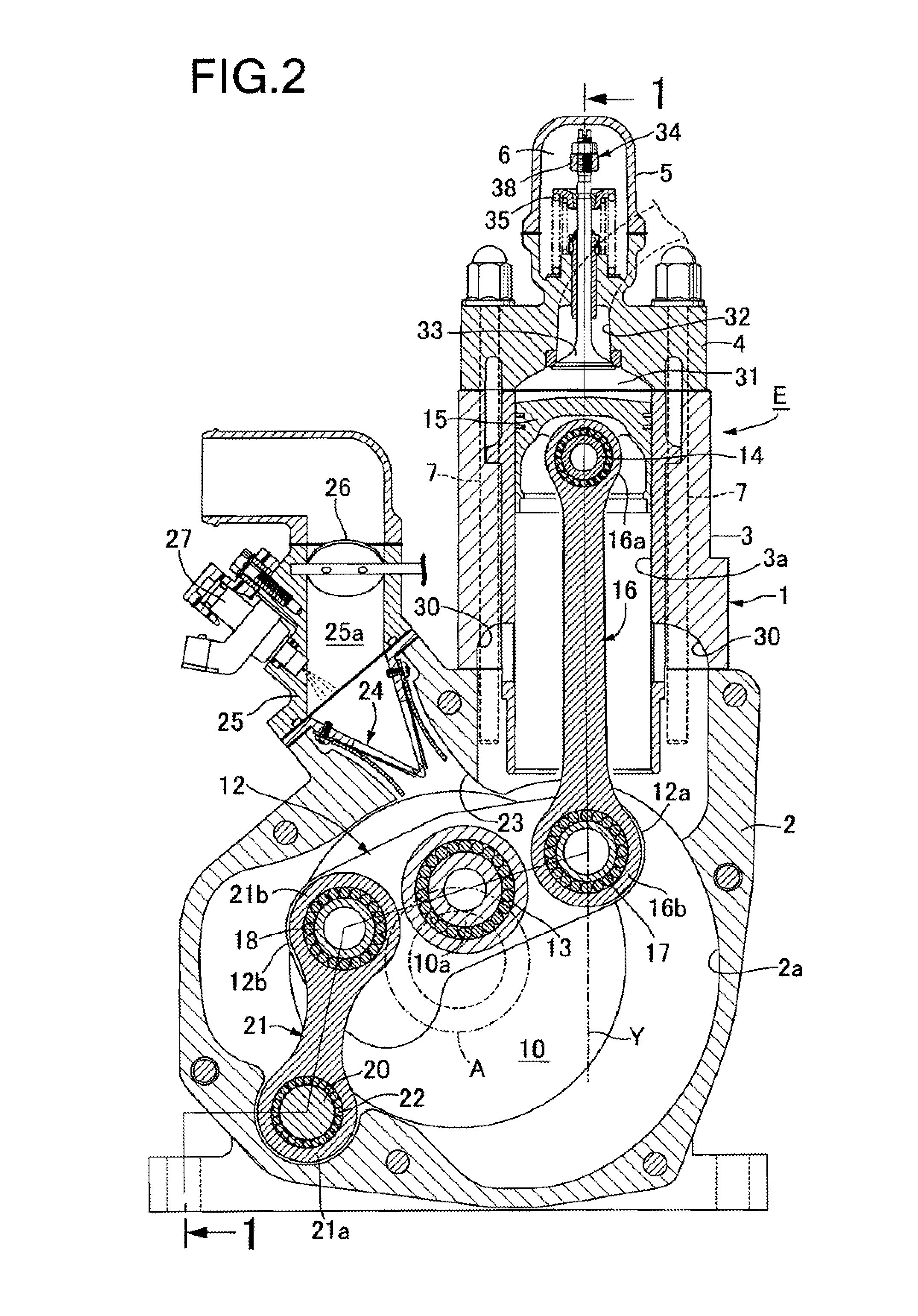
[0021]First of all, a first embodiment will be described. In FIGS. 1 and 2, an engine main body 1 of a premixed compression self-ignition engine E includes: a crankcase 2 whose inside is referred to as a crank chamber 2a; a cylinder block 3 provided upright and joined to an upper surface of the crankcase 2, the cylinder block 3 having a cylinder bore 3a therein; a cylinder head 4 joined to an upper end of the cylinder block 3; and a head cover 5 joined to an upper end of the cylinder head 4 and defining a valve operating chamber 6 between the cylinder head 4 and the head cover 5. The crankcase 2, the cylinder block 3, and the cylinder head 4 are fastened to each other with multiple stud bolts 7 implanted in the crankcase 2. The head cover 5 is fastened to the cylinder head 4 with multiple bolts 8.

[0022]In left and right side walls of the crankcase 2 (see FIG. 1), a crankshaft 10 whose crank portion is housed in the crank chamber 2a is supported with a pair of first bearings 11. Here...

second embodiment

[0037]FIG. 5 shows the present invention. The fuel injection valve 27 is attached to the cylinder block 3, and fuel is injected into the cylinder bore 3a to form an air-fuel mixture after the piston 15 closes the scavenging ports 30 in the upward stroke of the piston 15. Since other configurations and operations are the same as those in the above embodiment, components corresponding to those in the above embodiment are denoted by the same reference symbols in FIG. 5, and overlapping descriptions are omitted.

[0038]FIG. 6 shows a third embodiment of the present invention. The fuel injection valve 27 is attached to the crankcase 2, and fuel is injected into the scavenging ports 30. Since other configurations and operations are the same as those in the first embodiment, components corresponding to those in the above embodiment are denoted by the same reference symbols in FIG. 6, and overlapping descriptions are omitted.

[0039]It should be noted that the present invention is not limited t...


PUM


Abstract

In a premixed compression self-ignition engine which is compact but capable of exerting a high output, an intermediate portion of a trigonal link is rotatably supported on a crankpin, a large end portion of a connecting rod is connected to one end portion of the trigonal link, and a swing link swingably supported on a fulcrum shaft is connected to another end portion of the trigonal link. The engine includes: an intake port open to a crank chamber; a reed valve mounted in the intake port; a scavenging port configured to guide fresh air from the crank chamber into a cylinder bore in a downward stroke of a piston; an exhaust port provided in a cylinder head and open to a top portion of the cylinder bore; and an exhaust valve configured to be opened before the piston opens the scavenging port in the downward stroke of the piston.

Description

BACKGROUND OF THE INVENTION[0001]1. Field of the Invention[0002]The present invention relates to an improvement of a premixed compression self-ignition engine.[0003]2. Description of the Related Art[0004]Heretofore, premixed compression self-ignition engines have been employed in four-cycle engines as disclosed in Japanese Patent Application Laid-open No. 2003-269232.SUMMARY OF THE INVENTION[0005]Conventional premixed compression self-ignition four-cycle engines are characterized by their “high compression ratio” and “A / F lean combustion,” and achieve a high thermal efficiency and low NOx emission. However, it is known that an operating range of such premixed compression self-ignition four-cycle engines is limited because it is difficult to control combustion under practical conditions, and that an usable load is limited, making it difficult to ensure an output, because knocking occurs at high loads. Methods for improving a thermal efficiency include a method in which a compact comb...

Claims


Application Information

Patent Timeline
Patent Type & Authority Applications(United States)
IPC IPC(8): F16C7/02
CPCF16C7/023F02B1/12F01B9/02F02B75/32F02B2075/025F02B25/04F16C9/02
Inventor SHIMIZU, YASUHIROWATANABE, SEIYAMADA, YOSHIKAZUKAWAI, TORU
Owner HONDA MOTOR CO LTD
Learn More