Automated rod manipulator

a manipulator and automatic technology, applied in the direction of drilling rods, drilling pipes, drilling casings, etc., can solve the problems of difficult to automate the complete rod handling cycle, one of the more dangerous jobs of workers, and the difficulty of manual handling and manipulation of drilling rods by workers, so as to achieve convenient configuration

Active Publication Date: 2014-07-31
LAYNE MINERALS LLC
View PDF2 Cites 44 Cited by
  • Summary
  • Abstract
  • Description
  • Claims
  • Application Information

AI Technical Summary

Benefits of technology

[0007]The present invention is related to an Automated Rod Manipulator (ARM) system for use on drilling rigs (earth boring rigs) to provide safe, hands-free manipulation of a drill rod section back and forth between a drilling position that is within the drill rig mast and a storage position wherein the drill rod section is stored in a magazine located near the drill rig. The ARM is not limited to manipulating only a drill rod section but can also be used for handling core sampling barrels and other tubular members which may be used during a drilling process. A person of skill in the art will appreciate that the ARM may be easily configured and adapted to be used for drilling in the mineral, water, geotechnical, environmental, petroleum, and natural gas industries. The present disclosure describes one embodiment directed towards an ARM for use on a diamond core drilling rig. The principal components of the system may include: an arm, a carriage, and a drill rod storage magazine which may be applied across a number of industries.

Problems solved by technology

The manual handling and manipulation of drilling rod by workers is one of the more dangerous jobs associated with drilling into the earth's crust across all industries.
Consequently, this manual handling of the swivel has made it problematic to automate the complete rod handling cycle in a totally hands-free manner for the chuck-drive drill rigs.

Method used


Image

  • Automated rod manipulator
  • Automated rod manipulator
  • Automated rod manipulator

Examples


Embodiment Construction

[0041]The following detailed description of the present invention references the accompanying drawing figures that illustrate specific embodiments in which the invention can be practiced. The embodiments are intended to describe aspects of the present invention in sufficient detail to enable those skilled in the art to practice the invention. Other embodiments can be utilized and changes can be made without departing from the spirit and scope of the present invention. The present invention is defined by the appended claims and, therefore, the description is not to be taken in a limiting sense and shall not limit the scope of equivalents to which such claims are entitled.

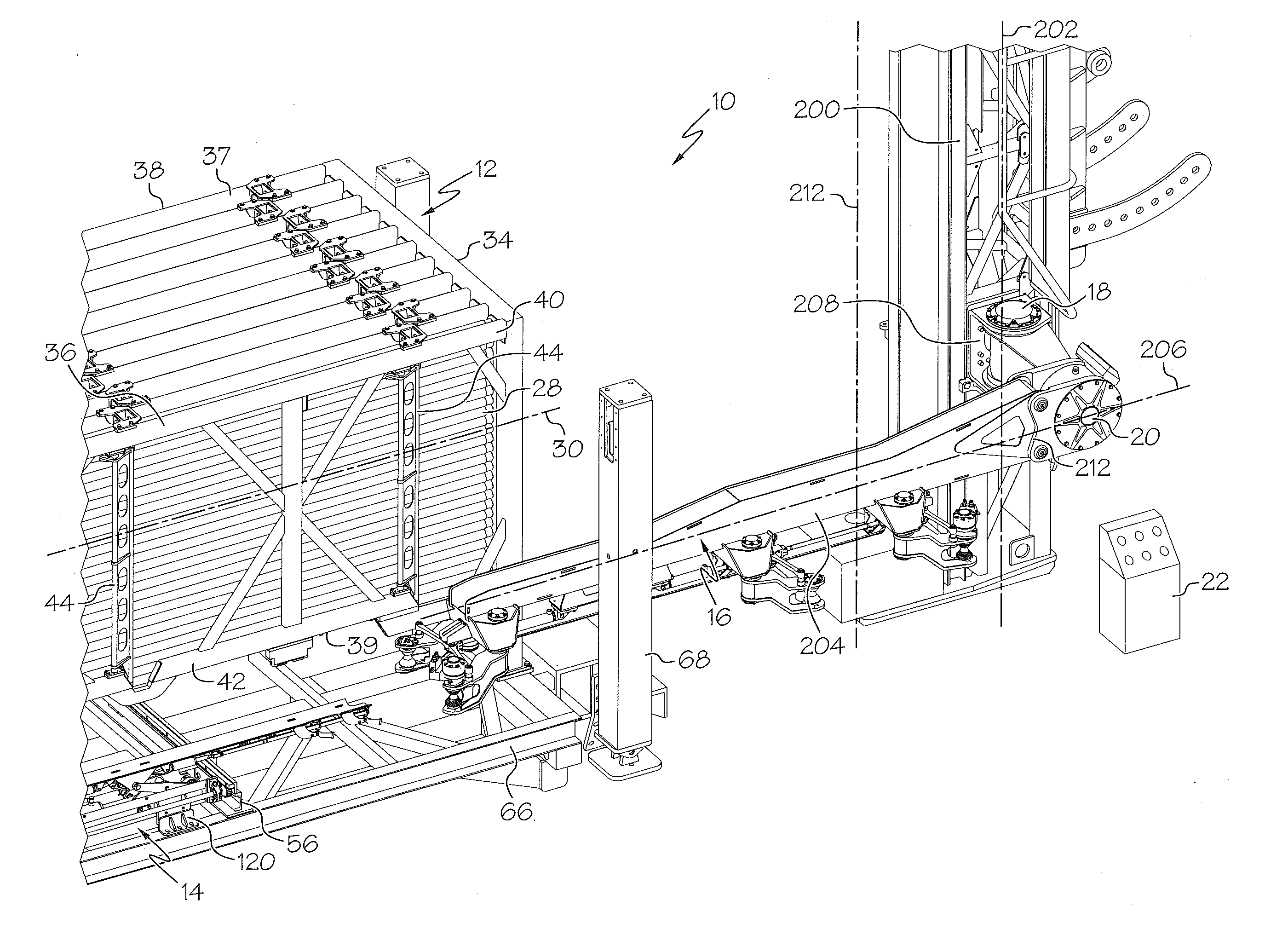
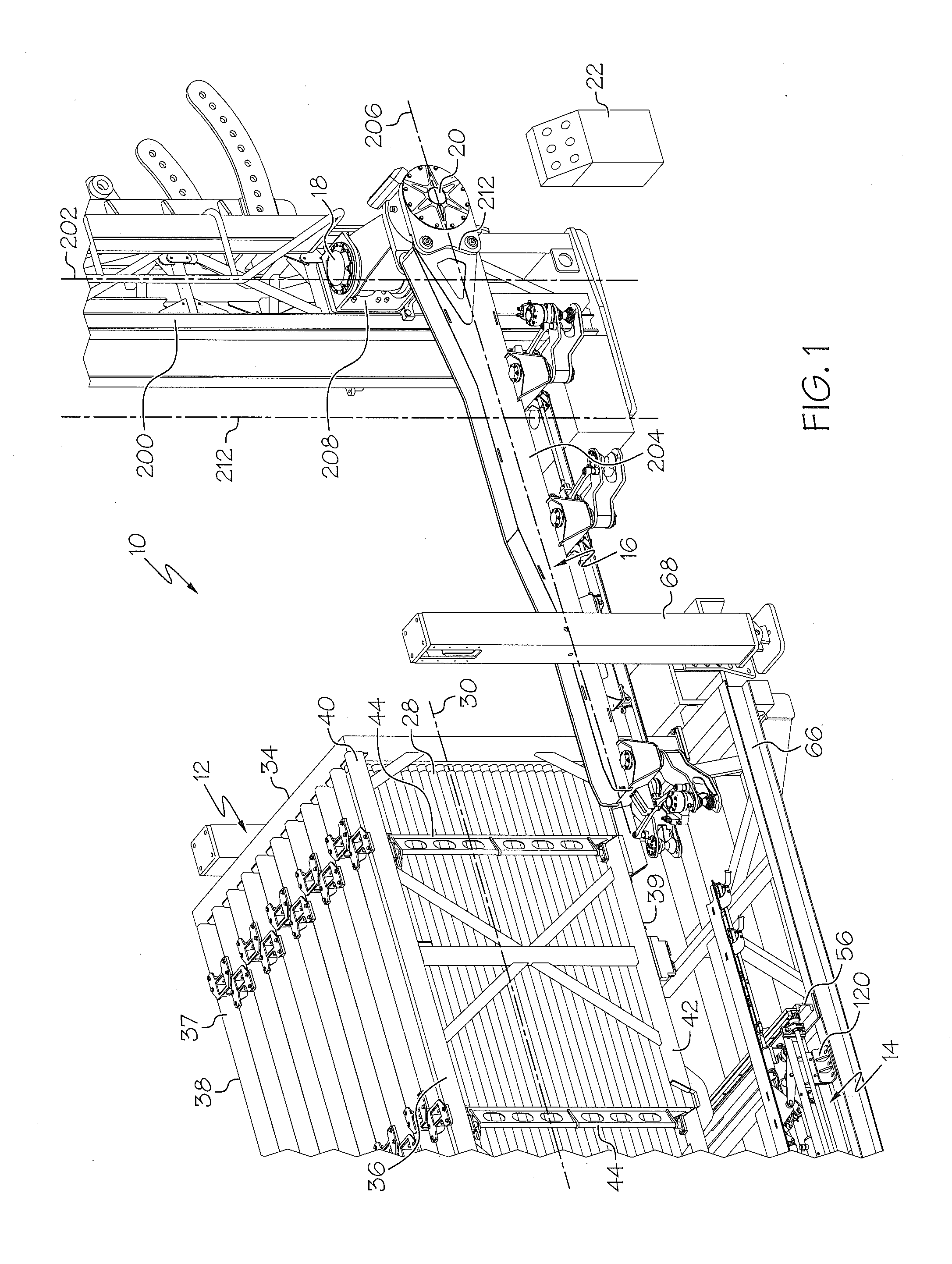
[0042]The present invention is directed toward an automated drill rod manipulator 10 that can be used in any subterranean drilling application. Automated drill rod manipulator 10 may be referred to herein as an automated rod manipulator or an “ARM” and such ten is may be used interchangeably. As shown in FIG. 1, auto...


PUM


Abstract

An automated rod manipulator system for moving a drill rod section from a storage magazine to a drill rig and connecting the drill rod to a drill string of the drill rig without manual manipulation of any parts. The automated rod manipulator system may comprise a magazine to store and dispense a plurality of drill rod sections, a carriage to convey one of the plurality of drill rod sections from the magazine to a transfer position; and a gripping arm coupled to a drill rig mast of a drilling rig, the gripping arm operable to convey one of the plurality of drill rod sections from a transfer position to a position aligned with a spindle center line of the drilling rig. The automated rod manipulator may also include a control system and an alignment assembly for aligning the drill rod section on a spindle centerline of the drill rig.

Description

CROSS-REFERENCE TO RELATED APPLICATIONS[0001]This application claims the benefit of U.S. Provisional Patent Application No. 61 / 757,009 filed Jan. 25, 2013, and U.S. Provisional Patent Application No. 61 / 785,365 filed Mar. 14, 2013. The entire disclosures of U.S. Provisional Patent Application Nos. 61 / 757,009 and 61 / 785,365 are hereby incorporated by reference.BACKGROUND OF THE INVENTION[0002]1. Field of the Invention[0003]The present invention is in the field of drilling into the earth's crust, such as to discover and extract oil, minerals, water, or other natural resources.[0004]2. Description of Related Art[0005]The manual handling and manipulation of drilling rod by workers is one of the more dangerous jobs associated with drilling into the earth's crust across all industries. Thus, to increase the safety of drilling rig workers, thereby reducing down-time associated with injuries and potential liability, there is a need in the art for a system that automatically retrieves a dril...

Claims


Application Information

Patent Timeline
Patent Type & Authority Applications(United States)
IPC IPC(8): E21B19/20
CPCE21B19/20E21B19/155E21B19/15E21B19/24E21B19/14
Inventor SMITH, BRIANCAMPANINI, STEFANOVITALI, GIANMARIAMAGGERT, JAMESMANDER, PAUL
Owner LAYNE MINERALS LLC
Why Eureka
Try Eureka