Fixed Printhead Fused Filament Fabrication Printer and Method

a printing printer and fused filament technology, applied in the direction of additive manufacturing processes, applications, manufacturing tools, etc., can solve the problems of extremely expensive printing printers and only being purchasable by large companies, and achieve the effect of increasing printing speed

Inactive Publication Date: 2014-07-31
RADIANT FABTION
View PDF19 Cites 65 Cited by
  • Summary
  • Abstract
  • Description
  • Claims
  • Application Information

AI Technical Summary

Benefits of technology

[0007]The fused filament fabrication printer of this invention uses one or a plurality of fixed printing heads which are mounted to a structure under which a print or build platform is disposed. The build platform may be in the form of a circular disk mounted for rotation about a z-axis, for linear motion along a radial or y-axis direction perpendicular to the z-axis and for linear motion along the z-axis between successive print planes. The build platform is rotated and scanned in a radial direction to construct each layer of the model. The platform can be rotated by a stepper motor or a motor continuously to deposit arcs of extruded material or with varying speeds and directions to print fine details. The build platform is moved linearly to reposition the fixed extruders over the platform to print a complete layer. Because the printing heads are fixed, multiple printing heads are easily affixed with respect to the build platform. Printing heads using the same material enable parallel material deposition to increase printing speed, while heads using different materials permit the simultaneous deposition of those materials on the build platform. The final degree of freedom is provided by the stepper motors or motors moving the platform along the z-axis to move the build platform to the next print plane.

Problems solved by technology

Initially such printers were extremely expensive, purchasable only by large companies, or accessible by outsourcing a 3-D model file to a fused filament fabrication printer or a competing technology, such as stereolithography as described in U.S. Pat. No. 4,575,330.

Method used


Image

  • Fixed Printhead Fused Filament Fabrication Printer and Method
  • Fixed Printhead Fused Filament Fabrication Printer and Method
  • Fixed Printhead Fused Filament Fabrication Printer and Method

Examples


Embodiment Construction

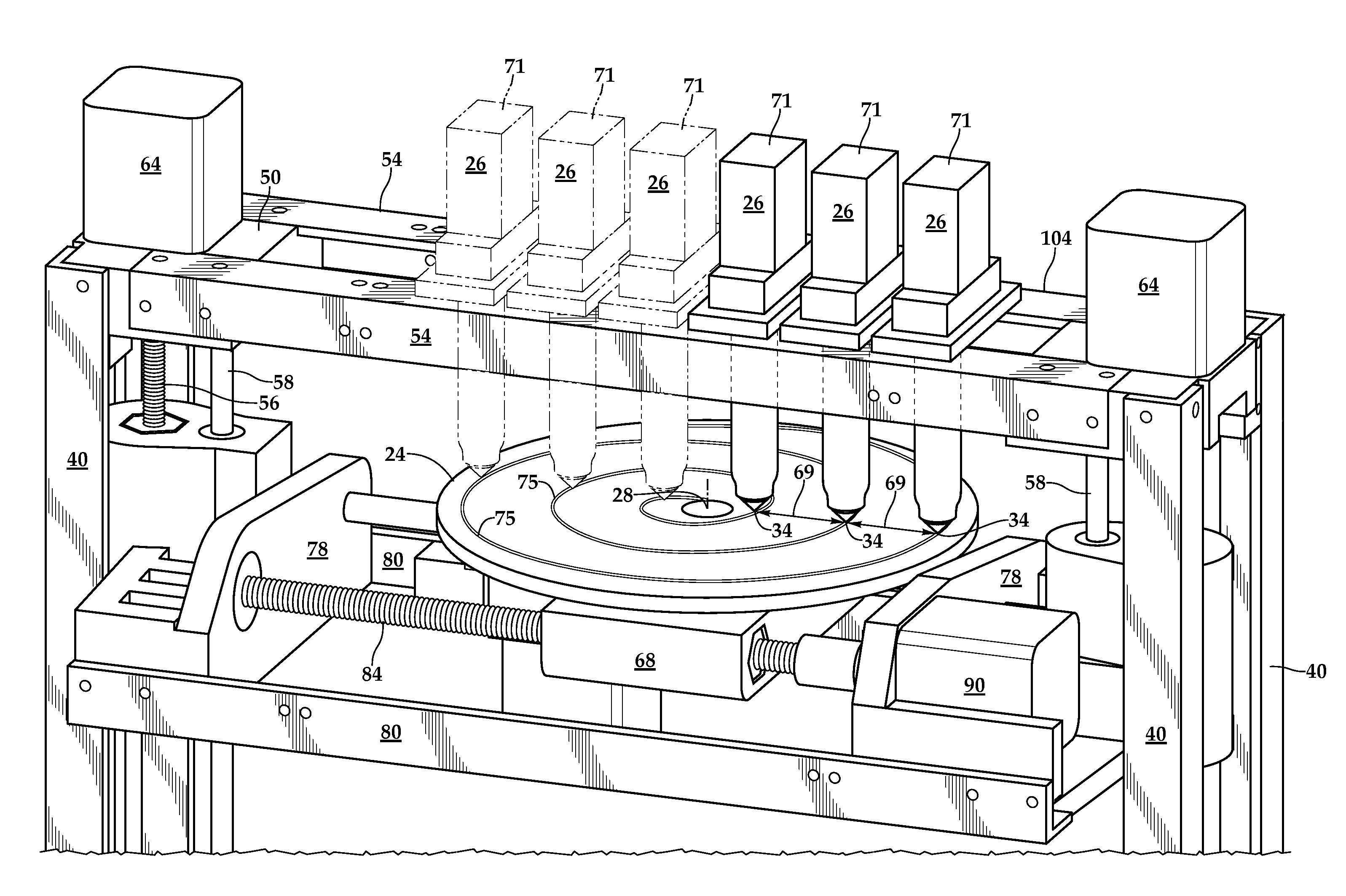
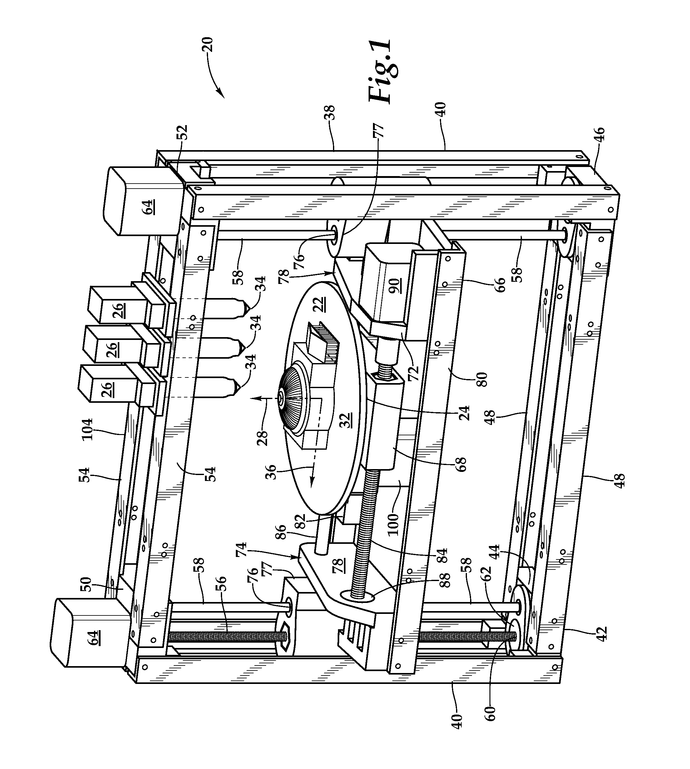
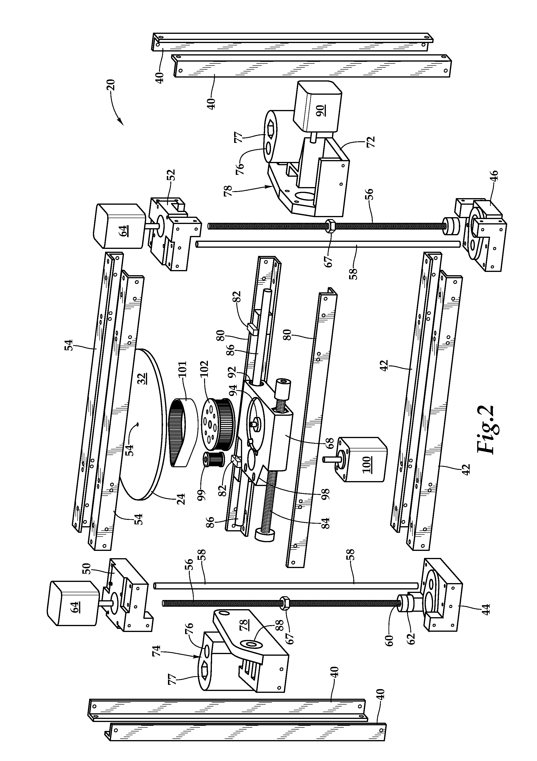
[0017]Referring more particularly to FIGS. 1-4 wherein like numbers refer to similar parts, a fused filament fabrication printer 20 is shown in FIG. 1. The printer 20 provides movement along three degrees of freedom to position various portions 22 of a printer build platform 24 beneath a plurality of printheads 26. The printheads 26 have tips 34 through which thermoplastic polymers, or metals are extruded. The three degrees of freedom start with a first degree of freedom: rotation of the build platform 24. The build platform defines a start-print plane or surface 32. A second degree of freedom is provided by linear motion along a radius or y-axis 36 perpendicular to the z-axis 28. A third degree of freedom is provided by linear motion of the printer platform in a Z-direction along the z-axis 28. The build platform 24 is moved in the Z-direction so the surface 32 occupies parallel planes, each parallel to a plane defined by the tips 34 of the printheads 26.

[0018]The indexing of the t...


PUM

PropertyMeasurementUnit
diameteraaaaaaaaaa
widthaaaaaaaaaa
widthaaaaaaaaaa

Abstract

A fused filament fabrication printer uses a plurality of fixed printing heads mounted to a structure over a build platform on which the model is built by constructing each layer of the model as the build platform is indexed through a multiplicity of successive print planes. The build platform may be in the form of a circular disk mounted for rotation about a z-axis and for linear motion along the z-axis between successive print planes, and for linear motion along a y-axis which is a selected radial direction perpendicular to the z-axis. Because the printheads are fixed, multiple printheads are easily affixed with respect to the build platform along the same radial line defining the y-axis transverse to the selected radial direction along which the build platform moves.

Description

CROSS REFERENCES TO RELATED APPLICATIONS[0001]Not applicable.STATEMENT AS TO RIGHTS TO INVENTIONS MADE UNDER FEDERALLY SPONSORED RESEARCH AND DEVELOPMENT[0002]Not applicable.BACKGROUND OF THE INVENTION[0003]The present invention relates to extrusion-based 3-D printers, termed fused deposition modeling or fused filament fabrication printers, in general and more particularly to printers using a printhead which applies layers of thermoplastic (e. g. ABS, HDPE, PLA, PVA) to create models, prototypes, patterns, and production parts.[0004]Fused filament fabrication works on an “additive” principle by laying down material in layers. This technique was initially developed by S. Scott Crump in 1989 and is described in U.S. Pat. No. 5,121,329. Initially such printers were extremely expensive, purchasable only by large companies, or accessible by outsourcing a 3-D model file to a fused filament fabrication printer or a competing technology, such as stereolithography as described in U.S. Pat. N...

Claims


Application Information

Patent Timeline
Patent Type & Authority Applications(United States)
IPC IPC(8): B29C47/06B29C48/154B29C48/345
CPCB29C47/065B29C64/40B29C48/154B29C48/266B29C64/118B29C64/106
Inventor PATTERSON, NATHAN JAMESHARRIS, KEVIN LEE
Owner RADIANT FABTION
Why Eureka
Try Eureka