Ningbo Yinzhou Zhonghe Hualida Plastic Mould Factory

a plastic mould factory and a technology which are applied in the direction of metal-working machine components, manufacturing tools, shaping tools, etc., can solve the problems of inconvenient use of die pressing plate, inconvenient installation and connection, and more parts, so as to reduce the steps of processing, rational and practical overall structure, and reduce the effect of cos

Active Publication Date: 2014-07-31
NINGBO YINZHOU ZHONGHE HUALIDA PLASTIC MOLD FACTORY
View PDF17 Cites 3 Cited by
  • Summary
  • Abstract
  • Description
  • Claims
  • Application Information

AI Technical Summary

Benefits of technology

[0006]It is an object of the present invention to provide a die pressing plate which is simple in structure, fast and convenient to assemble and use and low in cost.
[0015]Compared with the prior art, in the present invention, the extension portion extends elastically when the blocking portion slide downwardly through the guiding groove, and the blocking portion is blocked by the bottom surface of the main body, thereby omitting the design of gusset plates, requiring fewer components and no thread forming and riveting, reducing the steps of processing, bringing convenience to the production and assembly, lowering the cost, and making the overall structure rational and practical.

Problems solved by technology

However, this pressing plate group has the following shortcomings that a gusset plate is required to connect the upper and lower cushion blocks together, and fastened onto the pressing plate, resulting in more parts and inconvenient installation and connection.
Moreover, the connection strength of the gusset plate is limited, resulting in inconvenient use of the pressing plate.
On the other hand, the die of the original connecting sleeve is omitted, resulting in lower manufacturing cost of the die pressing plate.
However, the improvement still has the following shortcomings that, as the hollow connector passes through the lower through hole and the main through hole to be detachably connected to the stopper, the number of the components may be further reduced; it is easily lost; and both the assembly and the use are not so fast and convenient, thus requiring further improvements and designs.

Method used


Image

  • Ningbo Yinzhou Zhonghe Hualida Plastic Mould Factory
  • Ningbo Yinzhou Zhonghe Hualida Plastic Mould Factory
  • Ningbo Yinzhou Zhonghe Hualida Plastic Mould Factory

Examples


Embodiment Construction

[0022]To enable a further understanding of the innovative and technological content of the invention herein, refer to the detailed description of the invention and the accompanying drawings below:

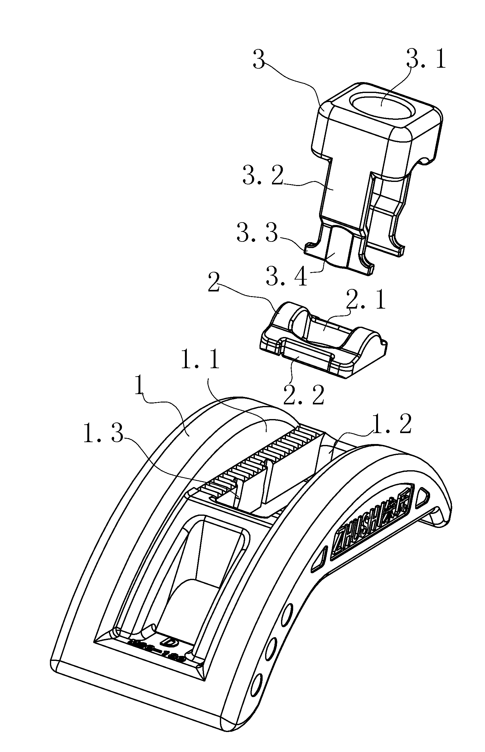
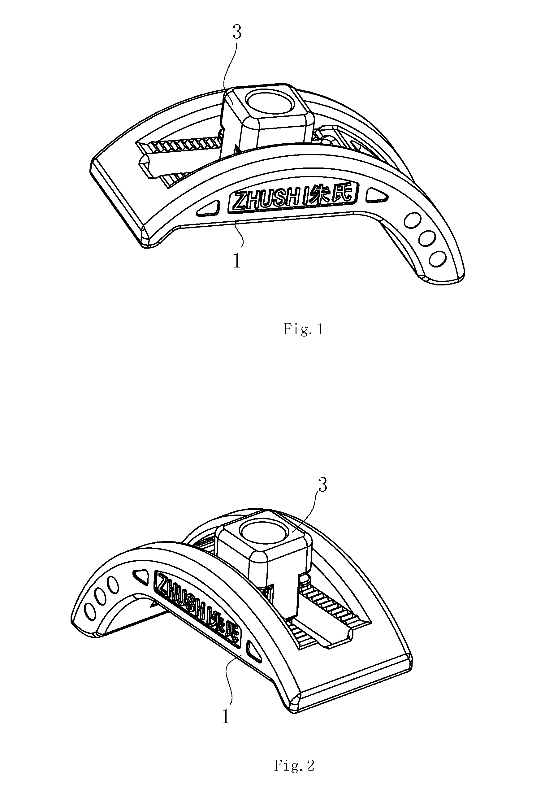
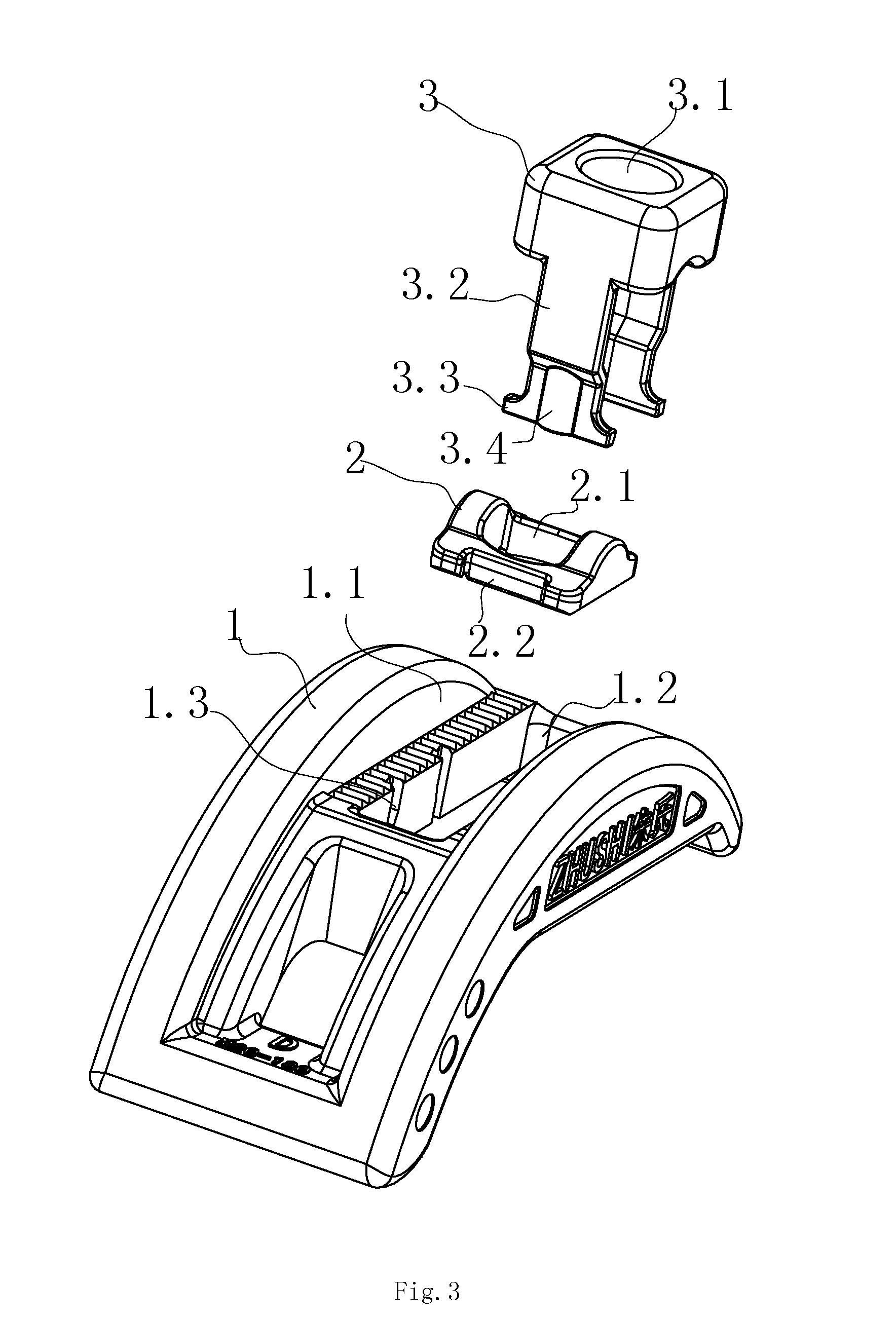
[0023]As shown in FIG. 1 to FIG. 6, a die pressing plate comprises: a main body 1 with a top surface and a bottom surface, an adjusting groove 1.1, and a main through hole 1.2 formed in a center of the adjusting groove 1.1 along a length of the main body 1; a lower cushion block 2 having a top curve surface and a lower through hole 2.1 for the screw to pass through defined by the top curve surface; and an upper cushion block 3 disposed on top of the lower cushion block 2, the upper cushion block 3 having a top surface and a lower curve surface for engaging the top curve surface of the lower cushion block 2, an upper through hole 3.1 defined on the top surface of the upper cushion block 3 for the screw to pass through, the upper cushion block 3 engaged with the lower cushion block 2 is dispo...


PUM


Abstract

A die pressing plate including a main body, an adjusting groove, and a main through hole, each of the left or right surface of the main through hole has at least one guiding groove; a lower cushion block having a top curve surface; and an upper cushion block having a lower curve surface for engaging the top curve surface of the lower cushion block, at least one extension portion protruding away from the lower curve surface, the at least one extension portion having two blocking portions, the blocking portions of the at least one extension portion engage the at least one guiding groove, the at least one extension portion extends elastically when the blocking portion slide downwardly, and the blocking portion is blocked by the bottom surface of the main body. The die pressing plate is simple in structure, fast and convenient to assemble and use, and low in cost.

Description

RELATE APPLICATIONS[0001]This application is a national phase entrance of and claims benefit to PCT Application for Die Pressing Plate thereof, PCT / CN2012 / 000949, filed on Jul. 12, 2012, which claims benefit to Chinese Patent Application 201110272103.X, filed on Sep. 7, 2011. The specifications of both applications are incorporated here by this reference.FIELD OF THE INVENTION[0002]The present invention relates to a die pressing plate.DESCRIPTION OF THE PRIOR ART[0003]Die pressing plates are common fixtures in the mechanical processing industry. The traditional flat die pressing plates, due to causes, for example, the cushion blocks of which are likely to fall down and lose, have been gradually replaced by the existing die pressing plates of a variety of structures on the market.[0004]As shown in a Chinese Utility Model CN2380344Y (Patent No. is ZL99206225.X), a convenient pressing plate group for machines comprises a pressing plate providing with an elongated slot and a screw strun...

Claims


Application Information

Patent Timeline
Patent Type & Authority Applications(United States)
IPC IPC(8): B23Q3/06
CPCB23Q3/06B25B5/105B21D37/00
Inventor ZHU, HUAFENG
Owner NINGBO YINZHOU ZHONGHE HUALIDA PLASTIC MOLD FACTORY
Why Eureka
Try Eureka