Motor control device including electric storage device and resistance discharge device

Active Publication Date: 2014-07-31
FANUC LTD
View PDF19 Cites 18 Cited by
  • Summary
  • Abstract
  • Description
  • Claims
  • Application Information

AI Technical Summary

Benefits of technology

The present invention aims to provide a motor control device that can use energy stored in an electric storage device efficiently to protect the device during power failures. The technical effect is improved efficiency in energy use and protection during power failures.

Problems solved by technology

For this reason, some inconvenience occur.
However, in a case in which an electric storage device is boosted and charged by using a charging unit with a boosting function of charging an electric storage device at a voltage higher than a DC voltage at a DC link, there is a possibility that when DC power is started to be supplied from the electric storage device to the DC link immediately after power failure occurs at the AC power supply side of the rectifier, energy for the protection operation at the time of power failure is consumed by the resistance discharge device, and therefore, intended protecting operation is difficult to be performed.
At the time of power failure, electric power for driving motor is difficult to be supplied from the AC power supply side, and accordingly, the protecting operation is performed by energy stored in the electric storage device and the DC link.
However, when power failure occurs at the AC power supply side of the rectifier under motor rotation, energy of the electric storage device is difficult to be used effectively. FIG. 22A and FIG. 22B illustrate voltage fluctuation in the DC link and voltage fluctuation in the electric storage device when power failure occurs under motor rotation, and DC power is supplied from the electric storage device to the DC link, in a situation where the electric storage device is boosted and charged by using the charging unit with the boosting function. FIG. 22A illustrates a motor speed, and FIG. 22B illustrates voltages at the DC link and the electric storage device.
When power failure occurs under motor rotation, the protecting operation is started, and the motor is decelerated.
Accordingly, energy almost corresponding to a voltage from the initial charged voltage of the electric storage device to the resistance discharging operation stop level is wastefully consumed by the resistance discharge device.
In other words, a part of energy of the electric storage device stored for the protecting operation is wastefully consumed as heat energy by the resistance discharge device.
For this reason, energy efficiency is low.
There is a possibility that energy needed for the protecting operation is insufficient, depending on a consumption situation of DC power discharged from the electric storage device, the consumption being performed by the resistance discharge device.
When an energy storage capacitance of the electric storage device is designed to have a margin such that energy needed for the protecting operation does not become insufficient, a volume and cost of the electric storage device is increased.

Method used


Image

  • Motor control device including electric storage device and resistance discharge device
  • Motor control device including electric storage device and resistance discharge device
  • Motor control device including electric storage device and resistance discharge device

Examples


Embodiment Construction

[0063]In the following, a motor control device including an electric storage device and a resistance discharge device will be described by referring to the drawings. However, it should be understood that the present invention is not limited to embodiments illustrated in the drawings or described in the following.

[0064]In each embodied example described below, a motor control device that drives and controls a plurality of motors is described. However, the number of the driven and controlled motors does not particularly limit the present invention.

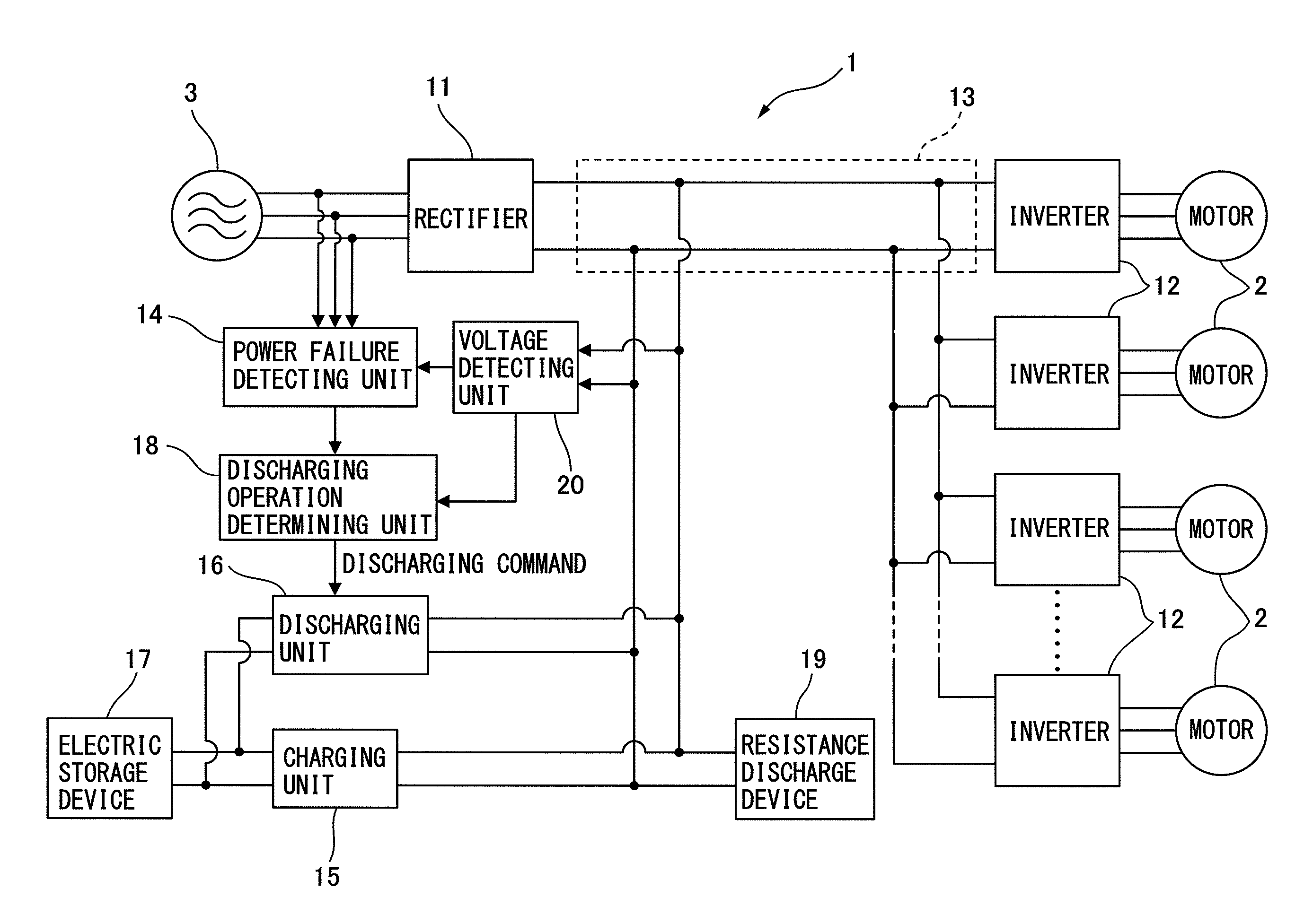
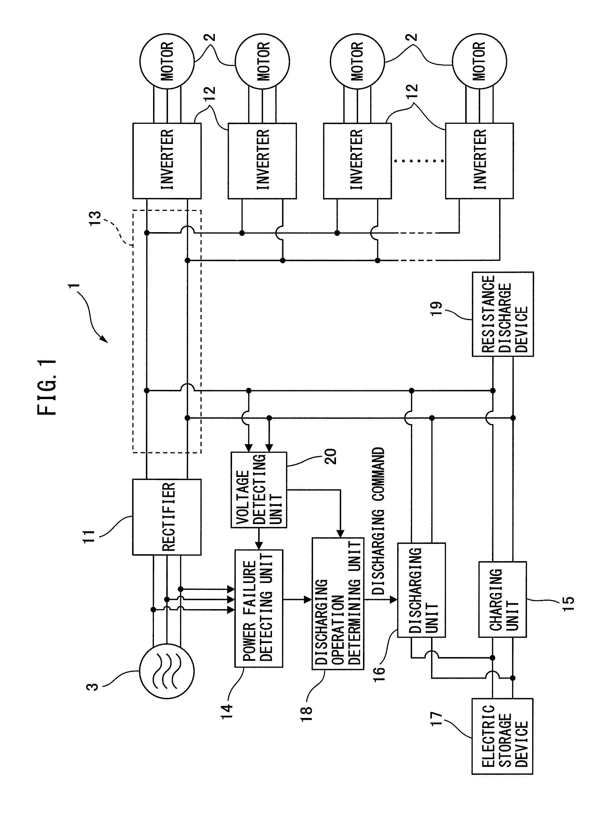
[0065]FIG. 1 is a circuit diagram illustrating a motor control device according to a first embodied example. In the following, elements to which the same reference symbols are attached in the different drawings mean the constituent elements with the same functions.

[0066]The motor control device 1 according to the first embodied example includes a rectifier 11, inverters 12, a power failure detecting unit 14, a voltage detecting unit 20, an e...


PUM


Abstract

A motor control device includes a rectifier, an inverter connected to the rectifier via the DC link, a power failure detecting unit detecting power failure, a voltage detecting unit detecting a DC voltage at the DC link, an electric storage unit storing DC power, a charging unit that can make charging by boosting to a voltage higher than the DC voltage, a discharging unit discharging DC power, a resistance discharge device that performs resistance discharging of DC power at the DC link when the DC voltage after power failure is equal to or higher than a predetermined start level and that does not perform resistance discharging when the DC voltage is equal to or lower than a predetermined stop level, and a discharging operation determining unit operating the discharging unit when the DC voltage at the DC link after power failure is equal to or lower than a predetermined threshold.

Description

BACKGROUND OF THE INVENTION[0001]1. Field of the Invention[0002]The present invention relates to a motor control device that converts alternating current (AC) power supplied from an AC side into direct current (DC) power to output the DC power, and then, further inverts the DC power into AC power for driving a motor to supply the AC power to the motor. In particular, the present invention relates to the motor control device that includes an electric storage device storing energy for protecting operation at the time of power failure, and a resistance discharge device consuming DC power of a DC link by resistance discharge.[0003]2. Description of the Related Art[0004]In a motor control device that drives a motor in a machine tool, a forging-heading machine, an injection molding machine, an industrial machine, or each of various robots, AC power input from an AC power supply side is converted into DC power once, and is then further inverted into AC power. This AC power is used as drive...

Claims


Application Information

Patent Timeline
IPC IPC(8): H02P3/14H02P3/12
CPCH02P3/12H02P3/14H02P3/22H02P5/74H02P2201/03
Inventor NIWA, MASAKAZUYAMAMOTO, KENTA
Owner FANUC LTD
Why Eureka
Try Eureka