Image processing apparatus and image pickup apparatus

Active Publication Date: 2014-07-31
CANON KK
View PDF12 Cites 32 Cited by
  • Summary
  • Abstract
  • Description
  • Claims
  • Application Information

AI Technical Summary

Benefits of technology

[0009]The present invention has been made in consideration of the circumstances described above and an object thereof

Problems solved by technology

However, when performance of an optical system is not particularly high as in the case of a compact camera, a depth of field cannot be reduced and a sufficient blur cannot be created.
Therefore, there is a possibility of generating an unnatural image in which, for example, a blur is added to an object even if a depth distance of the object is the same as that of an in-focus object (in other words, even if the object exists at a focal position).
Therefore, it is difficult to apply the method to general small-sized cameras and the like.
Another problem is that conditions such as camera parameters and a focal position must be spe

Method used


Image

  • Image processing apparatus and image pickup apparatus
  • Image processing apparatus and image pickup apparatus
  • Image processing apparatus and image pickup apparatus

Examples


first embodiment

Configuration of Image Pickup Apparatus

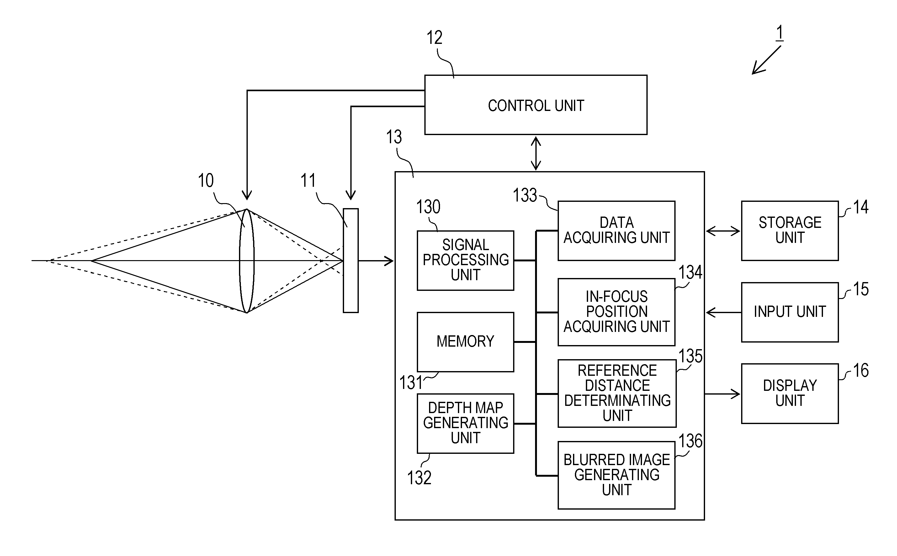
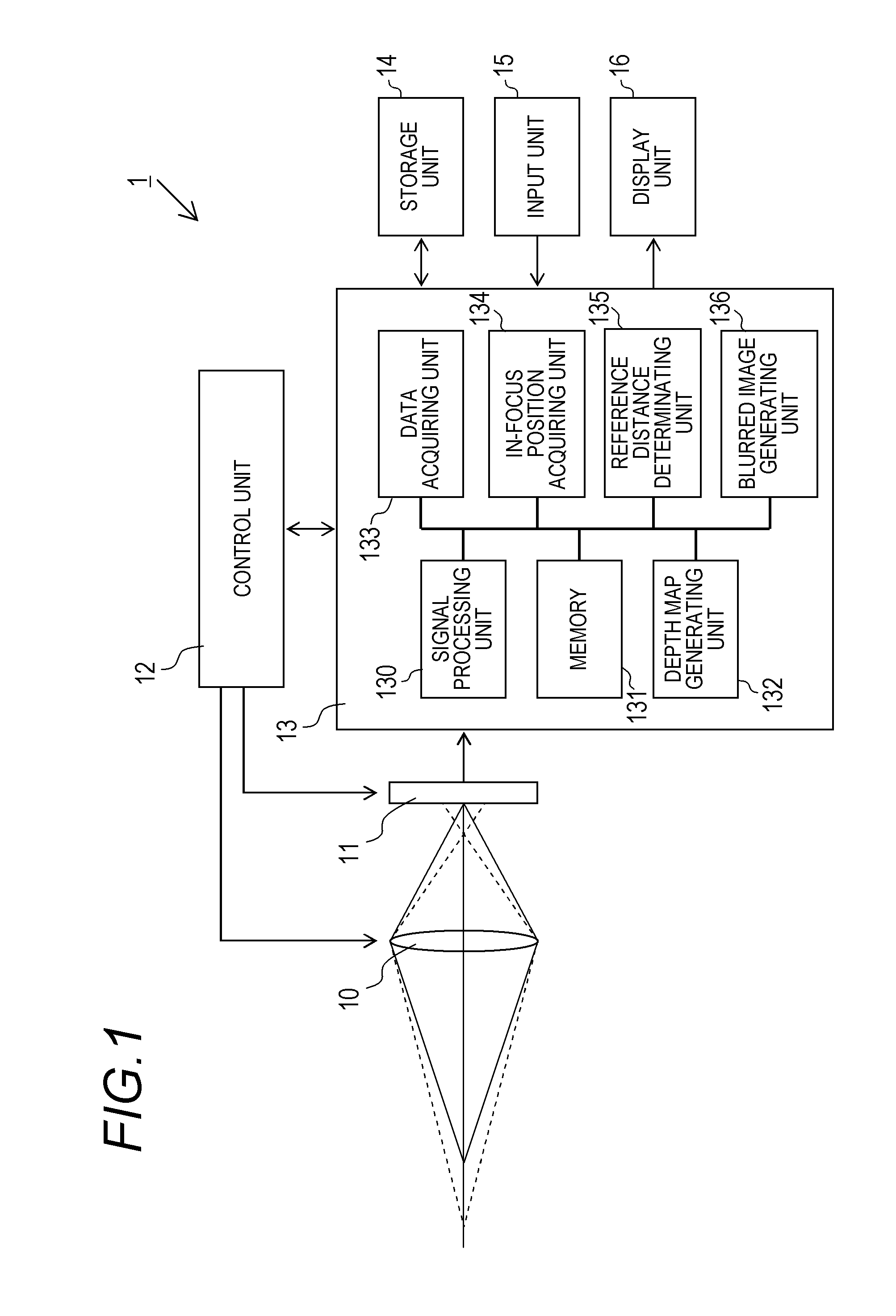
[0029]FIG. 1 is a diagram schematically showing a configuration of an image pickup apparatus according to a first embodiment of the present invention. An image pickup apparatus 1 includes an imaging optical system 10, an imaging element 11, a control unit 12, an image processing apparatus 13, a storage unit 14, an input unit 15, and a display unit 16.

[0030]The imaging optical system 10 is an optical system which is constituted by a plurality of lenses and which enables incident light to form an image on an imaging plane of the imaging element 11. A variable focus optical system is used as the imaging optical system 10, and thus automatic focusing can be performed by an autofocus function of the control unit 12. The autofocusing may adopt a passive system or an active system. The imaging element 11 is an imaging element including an image sensor such as a CCD or a CMOS. Alternatively, an imaging element having a color filter, a monochromatic ima...

second embodiment

[0049]Next, a second embodiment of the present invention will be described. While a coordinate of a range-finding point of autofocus is used as an in-focus position in the first embodiment, this method is problematic when performing focus-locked photography. Focus-locked photography refers to a technique in autofocus which involves performing photography by shifting a composition while keeping a focal position fixed. For example, by bringing a subject at the center of a screen into focus by automatic focusing and subsequently turning the camera to the right while half-pressing a shutter button, photography can be performed in a composition where the subject is positioned at a left end of the screen while keeping the distance of the subject in focus. In this case, since a coordinate of a range-finding point (the center of the screen) and a coordinate of an in-focus region (the left end of the screen) do not match, referencing the depth map based on the coordinate of the range-finding...

third embodiment

[0054]Next, a third embodiment of the present invention will be described. In the first and second embodiments, an in-focus position is acquired from autofocus information at the time of photography. In contrast, in the third embodiment, a prescribed object is detected from a photographed image and the detected position is assumed to be an in-focus position. The prescribed object may be any object as long as there is a high probability of the object being selected by the user as a subject. For example, a face, a half body, or a full body of a person is envisioned. This is because a face or a half body of a person is almost always brought into focus when photographing a portrait or taking a group photograph. The present embodiment utilizes this tendency. Hereinafter, an example of detecting a face of a person will be described.

[0055]The third embodiment differs from the first embodiment in the operations of the in-focus position acquiring unit 134. Specifically, the in-focus position...


PUM


Abstract

An image processing apparatus has: a depth map acquiring unit configured to acquire a depth map that records information indicating a depth distance corresponding to each point on a photographed image; an in-focus position acquiring unit configured to acquire an in-focus position on the photographed image; a reference distance determining unit configured to acquire a depth distance corresponding to the in-focus position from the depth map and sets the acquired depth distance as a reference distance; and an image processing unit configured to perform image processing on the photographed image by using the depth map and the reference distance.

Description

BACKGROUND OF THE INVENTION[0001]1. Field of the Invention[0002]The present invention relates to digital image processing and particularly to an image processing technique for performing image processing on a photographed image.[0003]2. Description of the Related Art[0004]A known photographic technique among various techniques of photography using a camera involves emphasizing a subject of interest by intentionally blurring portions other than the subject (such as a background). However, when performance of an optical system is not particularly high as in the case of a compact camera, a depth of field cannot be reduced and a sufficient blur cannot be created. In consideration thereof, techniques for generating an image with a blurred background or the like by subsequently adding a blur by digital image processing are recently being proposed. For example, an image pickup apparatus according to Japanese Patent Application Laid-open No. 2011-091570 determines a position on an image of ...

Claims


Application Information

Patent Timeline
IPC IPC(8): H04N5/262
CPCH04N5/2621G06T7/50H04N23/959G06V40/168G06T7/60G06T2207/30201
Inventor TANAKA, SHIN
Owner CANON KK
Why Eureka
Try Eureka