Planar lightwave circuit and optical receiver

Inactive Publication Date: 2014-07-31
NEC CORP
View PDF17 Cites 7 Cited by
  • Summary
  • Abstract
  • Description
  • Claims
  • Application Information

AI Technical Summary

Benefits of technology

The present invention is about a way to make devices called planar lightwave circuits and optical receivers that can improve the quality of signals. These improvements can make the devices work better and be more reliable.

Problems solved by technology

However, when thus realizing an optical receiving unit with a combination of bulk elements, it is difficult to adjust positional relationships between a plurality of bulk elements.
However, this method requires highly precise adjustment of the birefringence of the arms constituting the PBS.
Accordingly, the process of controlling the birefringence becomes complicated, and it is difficult to reduce the cost.

Method used


Image

  • Planar lightwave circuit and optical receiver
  • Planar lightwave circuit and optical receiver
  • Planar lightwave circuit and optical receiver

Examples


Embodiment Construction

[0031]Hereinafter, exemplary embodiments of the present invention will be described with reference to drawings.

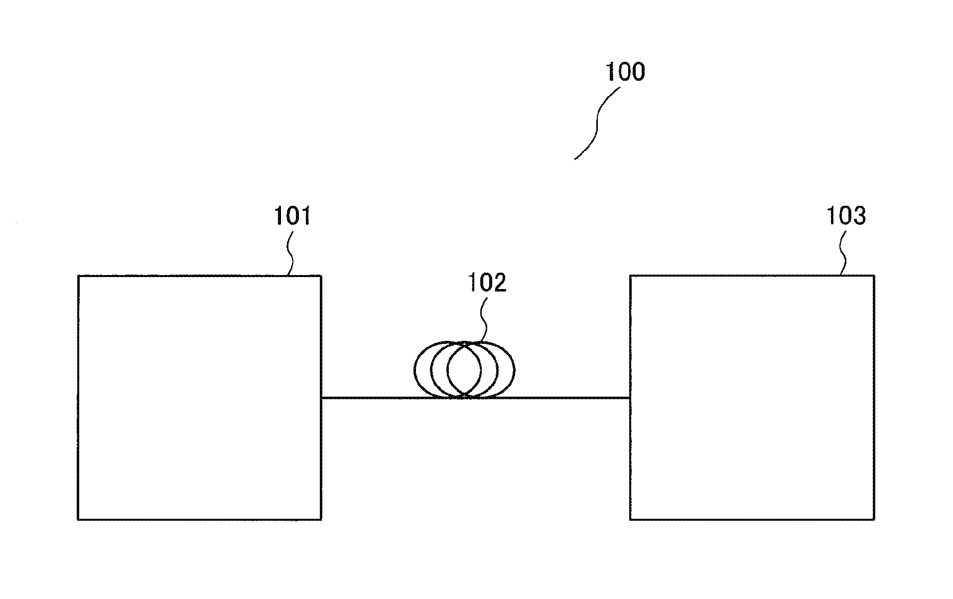
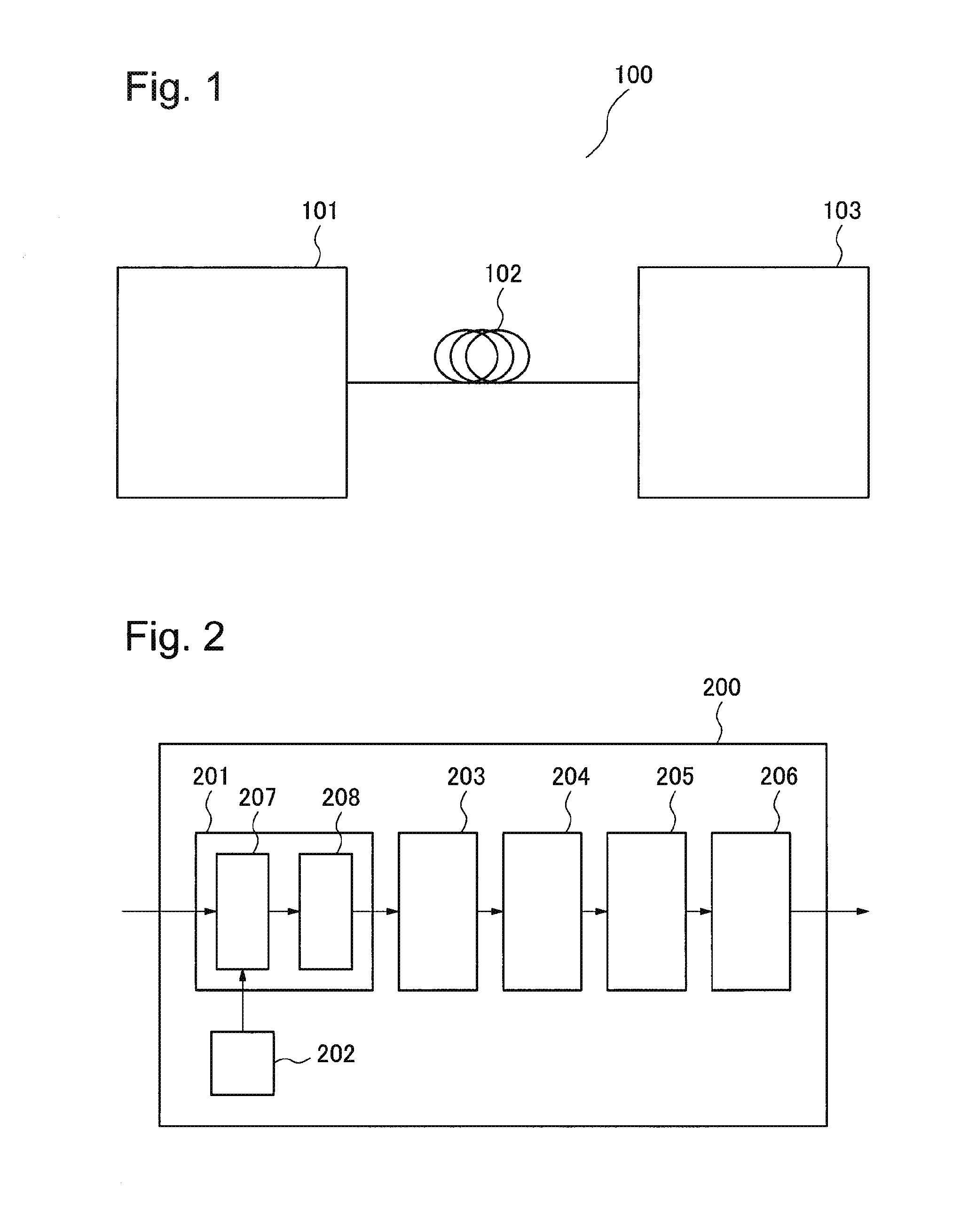
[0032]FIG. 1 is a functional block diagram of an optical transmission system 100 according to an exemplary embodiment of the present invention. The optical transmission system 100 includes an optical transmitter 101 which sends an optical signal modulated by polarization-multiplexed M-level phase shift keying (M is an integer equal to or larger than two), a transmission line 102 which transmits the optical signal sent from the optical transmitter 101, and an optical receiver 103 which receives the optical signal via the transmission line 102. Although M-level phase shift keying is used as an example in the present description, Amplitude Phase Shift Keying (APSK) and M-level Quadrature Amplitude Modulation (QAM) may also be used. Orthogonal Frequency Division Multiplexing (OFDM) may be employed as a transmission method, and polarization-multiplexed M-level phase shift keying...


PUM


Abstract

A planar lightwave circuit and an optical receiver which reduce degradation in signal quality is provided.A planar lightwave circuit includes: a substrate with a straight groove formed therein; a signal light input port which is formed in the substrate and receives signal light; a first planar filter part which is fitted into the groove and separates the signal light into a signal light component including a first polarization state and that including a second polarization state; a second planar filter part which is fitted into the groove and separates the local oscillator light into a local oscillator light component including the first polarization state and that including the second polarization state; a first interference part formed in the substrate; a second interference part which is formed on a side of the substrate opposite to the side of the first interference part across the groove; a first waveguide which is connected to the signal light input port and also to a reflection surface of the first planar filter part; a second and a third waveguide; a fourth waveguide which is connected to the local oscillator light input port and also to a reflection surface of the second planar filter part; and a fifth and a sixth waveguide.

Description

TECHNICAL FIELD[0001]The present invention relates to a planar lightwave circuit and an optical receiver for receiving polarization-multiplexed optical signals.BACKGROUND ART[0002]With the recent explosive increase in network traffic, ultra-high-speed optical transmission systems of 40 Gbit / s, beyond 100 Gbit / s have been investigated. For such ultra-high-speed optical transmission systems, active investigation has been conducted on digital coherent communication combining a phase modulation method with coherent detection and digital signal processing technology, which is superior in characteristics required for long haul optical fiber transmission, such as tolerance characteristics against optical signal noise, chromatic dispersion, and polarization mode dispersion.[0003]As a modulation method, Binary Phase Shift Keying (BPSK) and Quadrature Phase Shift Keying (QPSK) have attracted attention because of their excellent dispersion compensation tolerance.[0004]Further, in order to expa...

Claims


Application Information

Patent Timeline
IPC IPC(8): H04B10/69H04J14/06
CPCG02B6/4215G02B6/2773H04B10/615H04J14/06H04B10/697
Inventor WATANABE, SHINYA
Owner NEC CORP
Why Eureka
Try Eureka