
Solid battery and method for manufacturing the same

a technology of solid batteries and manufacturing methods, applied in the field of solid batteries, to achieve the effect of reducing the resistance of the battery, and reducing the voltage of the battery

Inactive Publication Date: 2014-07-31
TOYOTA JIDOSHA KK
View PDF4 Cites 3 Cited by
  • Summary
  • Abstract
  • Description
  • Claims
  • Application Information

AI Technical Summary

Benefits of technology

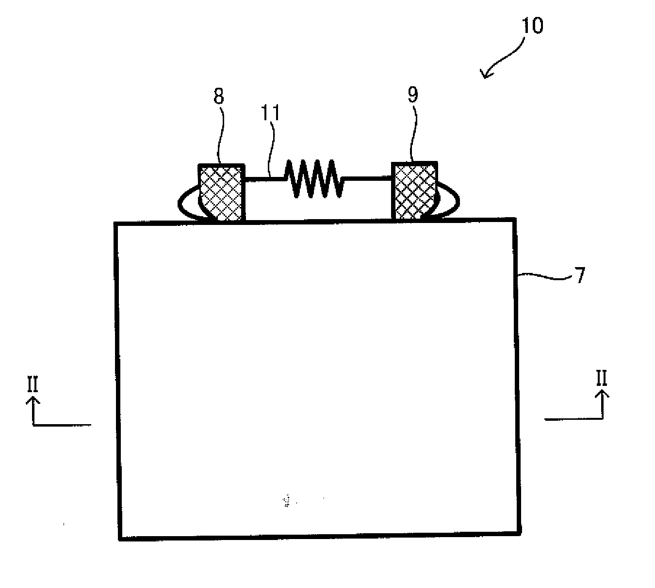
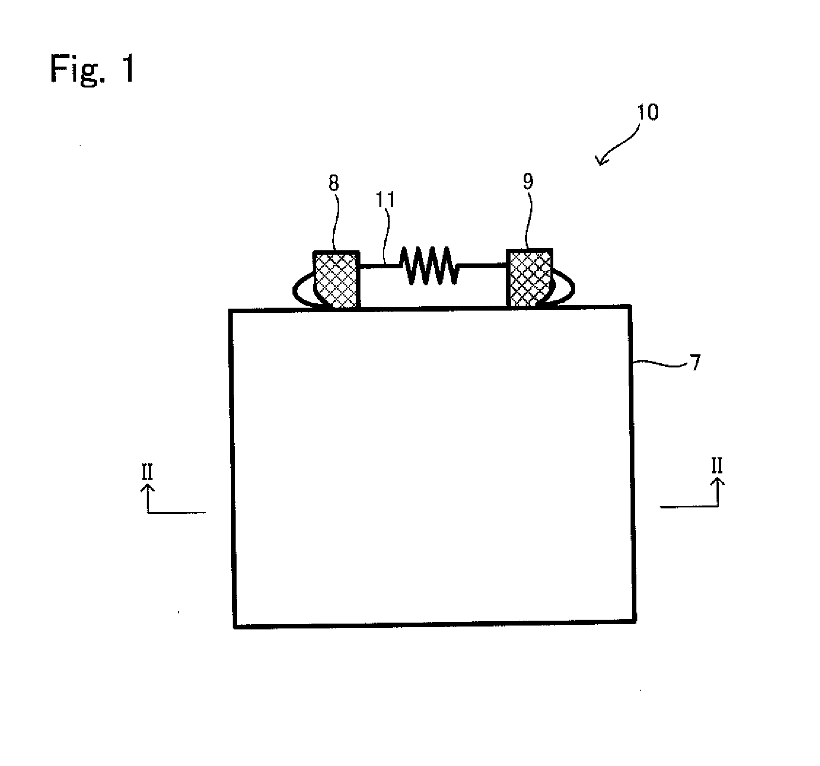
The present invention provides a solid battery that can improve output power. By reducing the battery voltage before charging, it is possible to reduce resistance of the battery and improve battery performance. The solid battery comprises a removable conductive member that connects the cathode layer and the anode layer. This enables easy reduction of battery voltage during manufacturing and assembly. The method of manufacturing the solid battery includes steps of connecting the cathode layer and the anode layer via the removable conductive member to reduce battery voltage. Overall, the present invention provides a technical solution for improving the performance and output power of solid batteries.

Problems solved by technology

However, since commonly used electrolytic solutions are flammable, it is necessary to have a system to ensure safety.

Method used


Image

  • Solid battery and method for manufacturing the same
  • Solid battery and method for manufacturing the same
  • Solid battery and method for manufacturing the same

Examples


example 1

[0047]After the electrode body was made by the above step, the electrode body was discharged with a constant current of 1.5 mA down to 0V, and thereafter discharged with a constant voltage of 0V for 10 hours . After that, confirming that the open-circuit voltage was 0.5V or less (specifically, 0.3V), the electrode was kept under a temperature of 25° C. for 24 hours.

[0048]Then, the electrode body was charged with a constant current of 0.3 mA up to 4.2V, and thereafter discharged with a current of 0.3 mA down to 2.5V. After that, the electrode body was charged to 3.6V to adjust the voltage then impedance analysis was carried out by using a solartron to obtain the resistance value. The result was shown in FIG. 5. The vertical axis of FIG. 5 represents resistance defining the resistance of the electrode body of the Comparative Example 2 described later as 1. It should be noted that, the discharge was performed with the constant current of 1.5 mA, but the current value of the constant cu...

example 2

[0049]The cathode layer and the anode layer of the electrode body produced by the above step were electrically connected by a removable conductive member (a copper wire), and kept with an open-circuit voltage of 0V for 10 hours. After that, confirming that the open-circuit voltage was 0.3V, the electrode body was kept under a temperature of 25° C. for 24 hours. Thereafter, the electrode body was charged with a constant current of 0.3 mA up to 4.2V, then discharged with a current of 0.3 mA down to 2.5V. After that, the electrode was charged to 3.6V to adjust the voltage then impedance analysis was carried out by using a solartron to obtain the resistance value. The result was shown in FIG. 5.


PUM

PropertyMeasurementUnit
voltageaaaaaaaaaa
voltageaaaaaaaaaa
pressureaaaaaaaaaa

Abstract

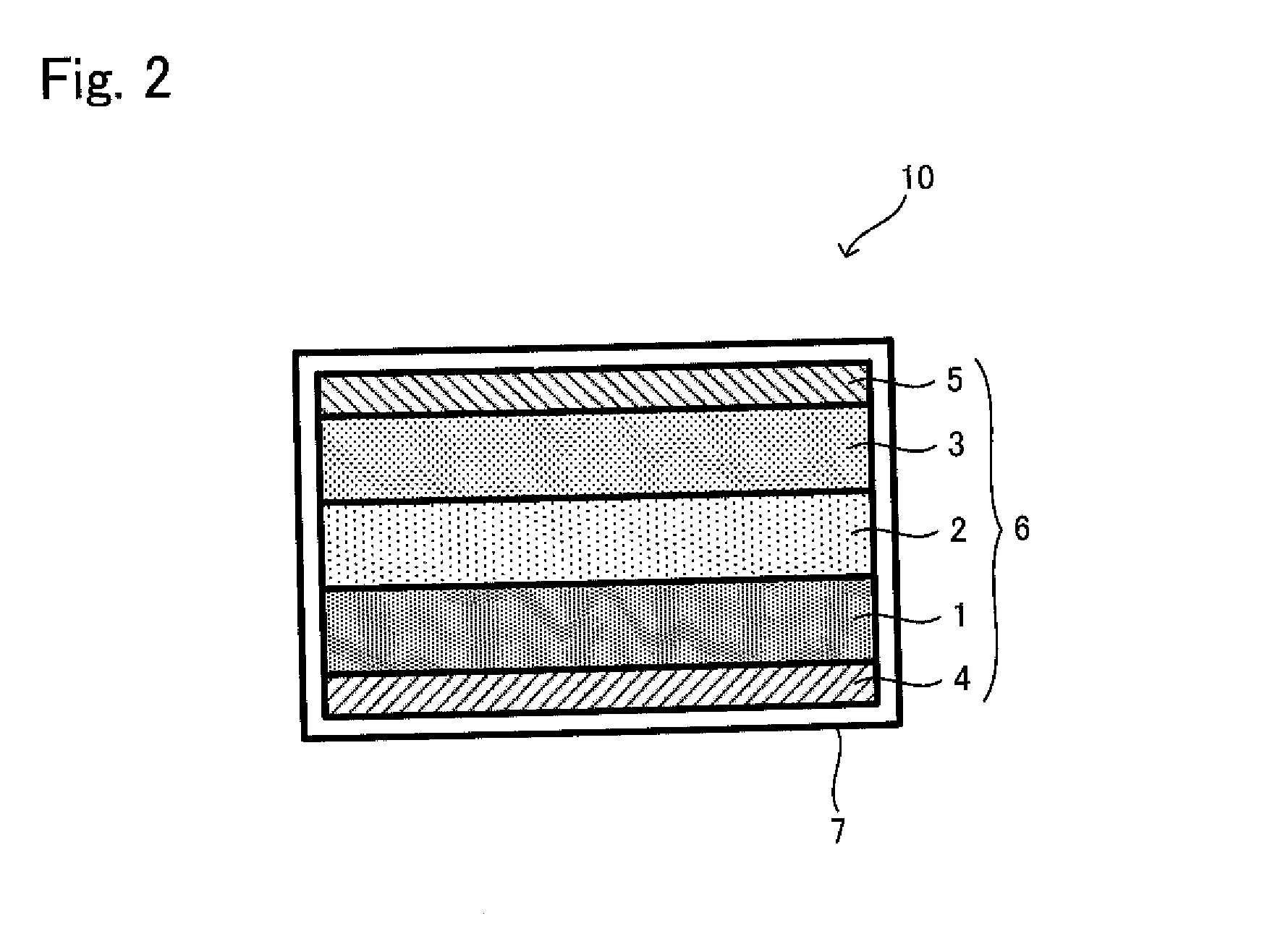
Provided is a solid battery which can improve output power and a method for manufacturing the solid battery, the present invention is a solid battery including an electrode body having a cathode layer, an anode layer, and a solid electrolyte layer disposed between the cathode layer and the anode layer and containing a sulfide-based solid electrolyte, wherein the cathode layer and the anode layer are connected via a removable conductive member, and a method for manufacturing the solid battery including the steps of: producing the electrode body; and connecting the cathode layer and the anode layer via the removable conductive member.

Description

TECHNICAL FIELD[0001]The present invention relates to a solid battery having a solid electrolyte and a method for manufacturing the solid battery.BACKGROUND ART[0002]A lithium-ion secondary battery (hereinafter sometimes referred to as “lithium secondary battery”) has a characteristic that it has a higher energy density and is operable at a high voltage compared to other secondary batteries. Therefore, it is used for information devices such as a cellular phone, as a secondary battery which can be easily reduced in size and weight. Nowadays there is also an increasing demand for the lithium-ion secondary battery to be used as a power source for large-scale apparatuses such as electric vehicles and hybrid vehicles.[0003]The lithium-ion secondary battery comprises a cathode layer, an anode layer, and an electrolyte layer disposed between them. An electrolyte to be used in the electrolyte layer is, for example, a non-aqueous liquid or a solid. When the liquid is used as the electrolyte...

Claims


Application Information

Patent Timeline
Patent Type & Authority Applications(United States)
IPC IPC(8): H01M10/0562H01M10/0525
CPCH01M10/0525H01M10/0562H01M10/0585H01M2300/002Y02E60/10Y10T29/49108Y02P70/50Y02T10/70
Inventor SUZUKI, YUSHIHAMA, SHIGENORI
Owner TOYOTA JIDOSHA KK
Learn More