Electrode structure for measuring bio-signal and apparatus for measuring electrocardiogram using the same

a biosignal and electrocardiogram technology, applied in the field of electrocardiogram electrocardiogram electrocardiogram electrocardiogram electrocardiogram electrocardiogram electrocardiogram electrocardiogram electrocardiogram electrocardiogram electrocardiogram electrocardiogram electrocardiogram electrocardiogram electrocardiogram electrocardiogram fast and stable

Inactive Publication Date: 2014-07-31
PUKYONG NAT UNIV IND ACADEMIC COOPERATION FOUND
View PDF2 Cites 17 Cited by
  • Summary
  • Abstract
  • Description
  • Claims
  • Application Information

AI Technical Summary

Benefits of technology

[0028]According to the electrode structure for measuring a bio-signal and the apparatus for measuring an electrocardiogram using the same of the present invention, it is possible to obtain quickly a stable electrocardiogram signal in such a way to reduce noise stabilization time at an earlier stage without producing any noises.
[0029]In addition, according to the electrode structure for measuring a bio-signal and the apparatus for measuring an electrocardiogram using the same of the present invention, it is possible to obtain quickly a stable electrocardiogram signal in such a way to lower the possibility of static electricity in an environment with low humidity in the air due to seasonal or geographical conditions.

Problems solved by technology

Since the above-mentioned measuring method requires the electrodes directly attached to a human body, it has problems such as a longer inspection time, an inconvenience caused to a testee and a disposal of wasted skin-contact electrodes.
The problem is that it requires a longer noise stabilization time until a clear signal without noises is obtained.

Method used


Image

  • Electrode structure for measuring bio-signal and apparatus for measuring electrocardiogram using the same
  • Electrode structure for measuring bio-signal and apparatus for measuring electrocardiogram using the same
  • Electrode structure for measuring bio-signal and apparatus for measuring electrocardiogram using the same

Examples


Embodiment Construction

[0035]The electrode structure for measuring a bio-signal and an apparatus for measuring an electrocardiogram using the same according to a preferred embodiment of the present invention will be described with reference to the accompanying drawings.

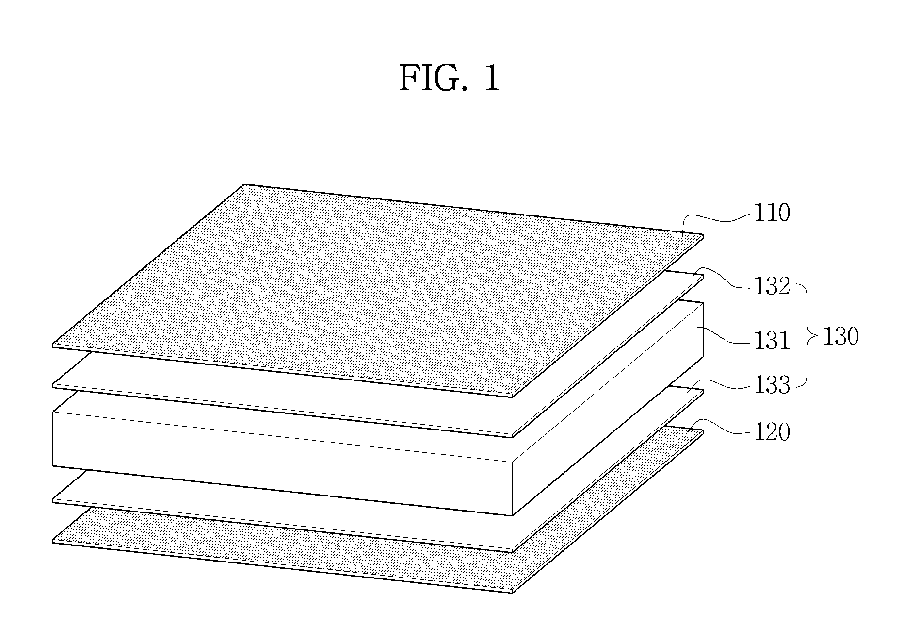
[0036]FIG. 1 is a view illustrating an electrode structure according to the present invention.

[0037]It seems that the long noise stabilization time taking place at an earlier stage in the conventional electric non-contact electrocardiogram measuring method is caused due to static electricity (which mainly resides in the electrodes or testee's clothes).

[0038]Meanwhile, it is known that the static electricity is directly related with humidity and the kinds of clothes. The higher the humidity, the fewer the occurrence of humidity. For example, in the winter when humidity is relatively higher, static electricity tends to occur more frequently as compared to the summer. In the summer when humidity is higher than 60% RH, static electricity dies o...


PUM


Abstract

The electrode structure for measuring a bio-signal and an apparatus for measuring an electrocardiogram using the same are disclosed. The electrode structure for measuring a bio-signal, comprises an electrode pad to measure bio-signals based on capacitive coupling between the electrode pad and human skin; an absorption layer formed at one side of the electrode pad; and a preamplifier which is electrically connected with the electrode pad and filters noise from the bio-signals from the electrode pad and amplifies and outputs the signals. Thus, the initial noise stabilization time can be reduced, and stable electrocardiogram signals can be obtained quickly without noises.

Description

CROSS-REFERENCE TO RELATED APPLICATION[0001]This application claims priority to Korean Patent Application No. 10-2013-0011175, filed on Jan. 31, 2013, and all the benefits accruing therefrom under 35 U.S.C. §119, the contents of which in its entirety are herein incorporated by reference.BACKGROUND[0002]1. Field[0003]The present invention relates to an electrode structure for measuring a bio-signal and an apparatus for measuring an electrocardiogram using the same, and in particular to an electrode structure and an apparatus for measuring an electrocardiogram using the same which make it possible to obtain quickly a stable electrocardiogram signal while reducing noise stabilization time at an earlier stage without producing any noises.[0004]2. Description of the Related Art[0005]Various electric bio-signals such as an ECG (Electrocardiogram) signal, a brain signal, an electrocardiogram signal, etc. are generally measured from a human body and is used for the sake of health care.[0006...

Claims


Application Information

Patent Timeline
Patent Type & Authority Applications(United States)
IPC IPC(8): A61B5/0408A61B5/00
CPCA61B5/6891A61B5/0408A61B5/0006A61B2562/0214A61B5/6893A61B5/25A61B5/263A61B5/277A61B5/7225A61B5/7217A61B5/28A61B2562/0209
Inventor CHUNG, WAN YOUNG
Owner PUKYONG NAT UNIV IND ACADEMIC COOPERATION FOUND
Why Eureka
Try Eureka