

Refrigeration cycle apparatus
- Summary
- Abstract
- Description
- Claims
- Application Information
AI Technical Summary
Benefits of technology
Problems solved by technology
Method used
Image

Examples
embodiment 1
Configuration of Air-Conditioning Apparatus
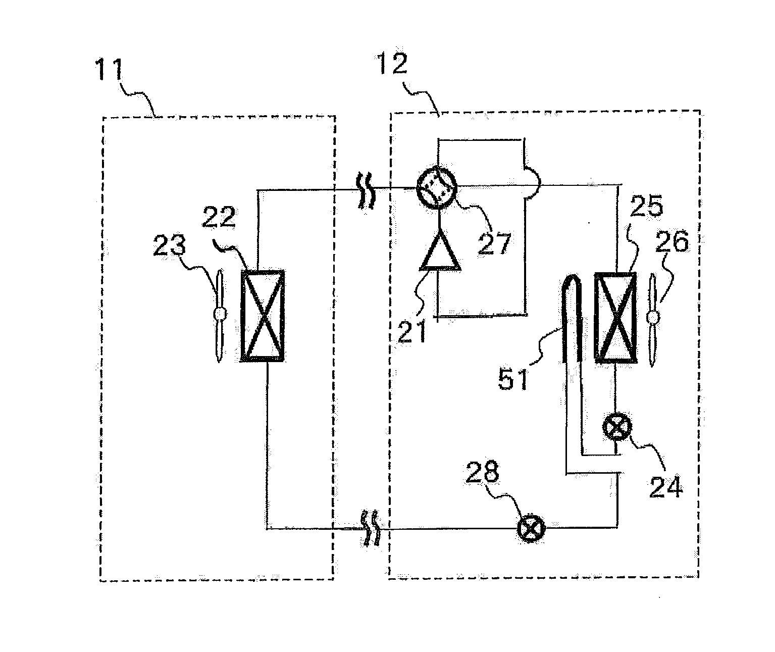
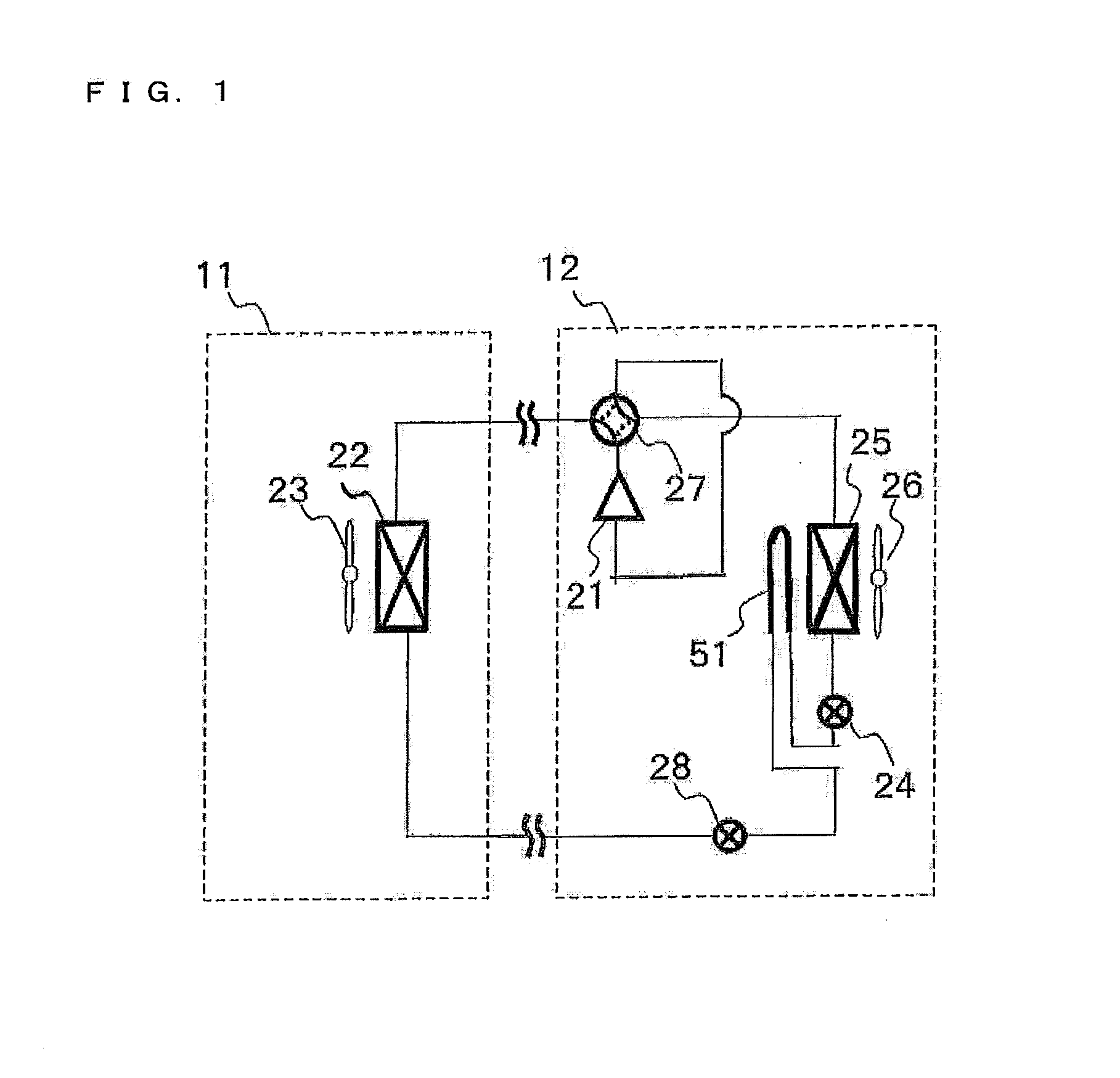
[0025]FIG. 1 illustrates a configuration of a refrigerant circuit in an air-conditioning apparatus according to Embodiment 1 of the present invention. While the present invention relates to refrigeration cycle apparatuses, an air-conditioning apparatus will be given as one example of the refrigeration cycle apparatuses in the description of Embodiment 1.
[0026]As illustrated in FIG. 1 the air-conditioning apparatus of Embodiment 1 is composed of an indoor unit 11 and an outdoor unit 12.
[0027]The indoor unit 11 includes an indoor heat exchanger 22 and an indoor fan 23. The outdoor unit 12 includes a compressor 21, first expansion means 24, outdoor heat exchanger 25, an outdoor fan 26, a four-way valve 27, second expansion means 28, and a heating unit 51.
[0028]Among these elements, the compressor 21, the four-way valve 27, the indoor heat exchanger 22, the second expansion means 28, the heating unit 51, the first expansion means 24, the outdoo...
embodiment 2
[0073]An air-conditioning apparatus according to Embodiment 2 will be described with a focus on differences from the air-conditioning apparatus according to Embodiment 1.
[Structure of Outdoor Unit 12]
[0074]FIG. 7 schematically illustrates a structure of an outdoor unit 12 in an air-conditioning apparatus according to Embodiment 2 of the present invention. FIG. 7 illustrates a rear view, a bottom view, and a right side view of the outdoor unit 12. In FIG. 7, the shape, arrangement, etc. of a heating unit 51 will be mainly described, and illustrations of other elements that constitute a refrigeration cycle, such as refrigerant pipes and devices, are partly omitted. The elements whose illustrations are omitted are basically similar to those of the outdoor unit 12 according to Embodiment 1 illustrated in FIG. 3.
[0075]An outdoor heat exchanger 25 is different from the outdoor heat exchanger 25 in the outdoor unit 12 of Embodiment 1, and is formed by one heat exchange unit subjected to wa...
embodiment 3
[0084]An air-conditioning apparatus according to Embodiment 3 will be described with a focus on differences from the air-conditioning apparatus according to Embodiment 1.
[Structure of Outdoor Unit 12]
[0085]FIG. 8 schematically illustrates a structure of an outdoor unit 12 in an air-conditioning apparatus according to Embodiment 3 of the present invention. FIG. 8 illustrates a rear view, a bottom view, and a right side view of the outdoor unit 12. In FIG. 8, the shape, arrangement, etc. of a heating unit 51 will be mainly described, and illustrations of other elements that constitute a refrigeration cycle, such as refrigerant pipes and devices, are partly omitted. The elements whose illustrations are omitted are basically similar to those of the outdoor unit 12 according to Embodiment 1 illustrated in FIG. 3.
[0086]As illustrated in FIG. 8, in the outdoor unit 12 in the air-conditioning apparatus of Embodiment 3, a groove 61 is provided in a portion of a drain pan 31 positioned just b...
PUM
| Property | Measurement | Unit |
|---|---|---|
| Temperature | aaaaa | aaaaa |
Abstract
Description
Claims
Application Information