Cooling assembly

a technology of cooling assembly and cooling chamber, which is applied in the direction of defrosting, domestic cooling apparatus, application, etc., can solve the problems of increasing the problem of climate, affecting the cooling power, and affecting the cooling effect of electronic components, so as to reduce the cooling power

Inactive Publication Date: 2014-08-07
ABB (SCHWEIZ) AG
View PDF0 Cites 3 Cited by
  • Summary
  • Abstract
  • Description
  • Claims
  • Application Information

AI Technical Summary

Benefits of technology

[0006]An exemplary embodiment of the present disclosure provides a cooling assembly which includes a device chamber, a cooling chamber separated from the device chamber, a heat exchanger, device chamber fan means, and control means. The heat exchanger includes a first portion located in the device chamber and a second portion located in the cooling chamber for transferring heat from the device chamber to the cooling chamber. The device chamber fan means are configured to generate a device chamber cooling medium flow including a first partial flow interacting with the first portion of the heat exchanger. The exemplary cooling assembly also includes first throttle means for regulating the first partial flow. The control means are configured to reduce a cooling power of the heat exchanger as a response to predetermined operating conditions by decreasing the first partial flow with the first throttle means.

Problems solved by technology

Humidity is harmful to many electronic components.
Humidity is an issue, for example, in solar power plants and wind power plants.
Challenging environments such as tropical or arctic climates increase problems caused by humidity.
Preventing humidity by means of heating induces extra cost.
Water absorbing materials are also expensive and their useful life is limited thereby further increasing cost.

Method used


Image

  • Cooling assembly
  • Cooling assembly
  • Cooling assembly

Examples


Embodiment Construction

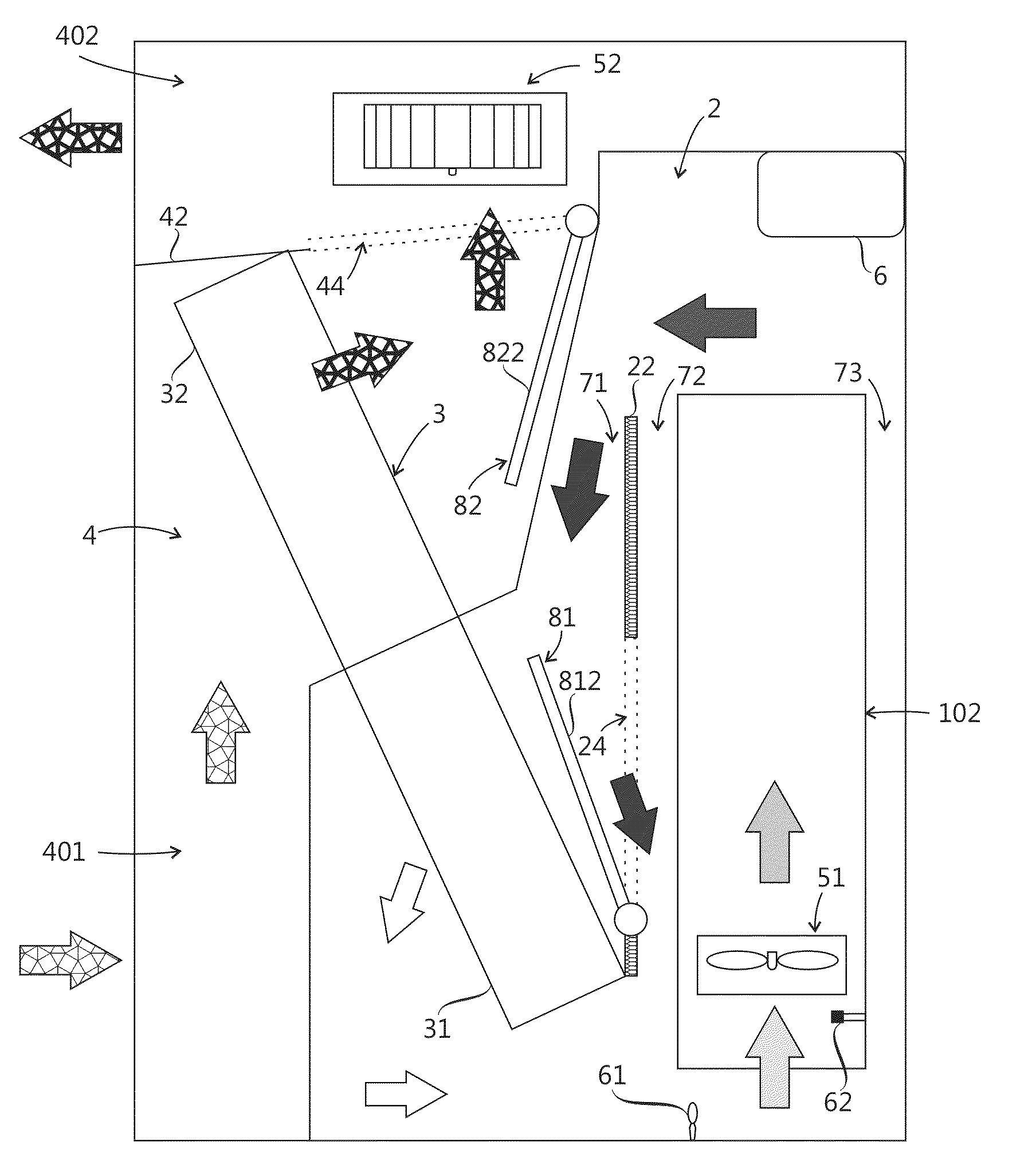
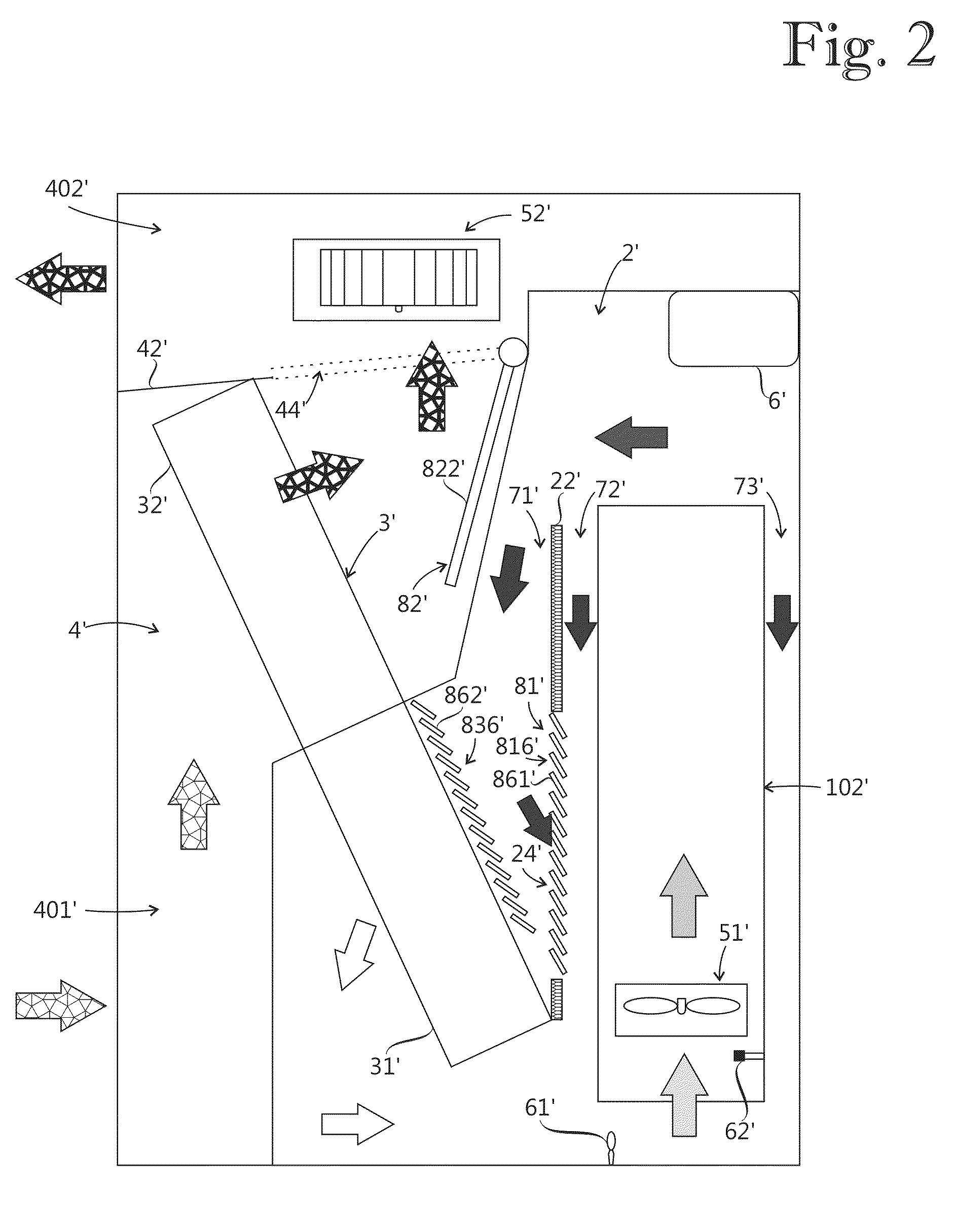
[0011]Exemplary embodiments of the present disclosure provide a cooling assembly which is capable of alleviating disadvantages caused by humidity.

[0012]Exemplary embodiments of the present disclosure are based on the idea of decreasing in predetermined operating conditions a relative humidity level in a device chamber by reducing a cooling power of a heat exchanger configured to transfer heat from the device chamber. The cooling power is reduced by a first throttle means capable of regulating a first partial flow of a cooling medium interacting with a first portion of the heat exchanger located in the device chamber. Exemplary embodiments of the present disclosure improve controllability of a heat exchanger by lowering a minimum cooling power of the heat exchanger. Decreasing cooling power of the heat exchanger raises the temperature in a device chamber thereby reducing relative humidity.

[0013]An advantage of the cooling assembly of the present disclosure is that a relative humidity...


PUM


Abstract

A cooling assembly includes a device chamber, a cooling chamber separated from the device chamber, a heat exchanger, a device chamber fan arrangement and a control unit. The heat exchanger includes a first portion located in the device chamber and a second portion located in the cooling chamber for transferring heat from the device chamber to the cooling chamber. The device chamber fan arrangement is configured to generate a device chamber cooling medium flow including a first partial flow interacting with the first portion of the heat exchanger. The cooling assembly also includes a first throttle arrangement for regulating the first partial flow. The control unit is configured to reduce a cooling power of the heat exchanger as a response to predetermined operating conditions by decreasing the first partial flow with the first throttle arrangement.

Description

RELATED APPLICATION[0001]This application claims priority under 35 U.S.C. §119 to European Patent Application No. 13153787.0 filed in Europe on February 4, 2013, the entire content of which is hereby incorporated by reference in its entirety.FIELD[0002]The present disclosure relates to a cooling assembly including a heat exchanger for transferring heat from a device chamber.BACKGROUND INFORMATION[0003]Humidity is harmful to many electronic components. Humidity is an issue, for example, in solar power plants and wind power plants. Challenging environments such as tropical or arctic climates increase problems caused by humidity.[0004]In a known cooling assembly, heating of a device chamber is used to prevent excessive humidity. It is also known to use water absorbing materials such as silica gel to remove humidity from a device chamber.[0005]Preventing humidity by means of heating induces extra cost. Water absorbing materials are also expensive and their useful life is limited thereby...

Claims


Application Information

Patent Timeline
Patent Type & Authority Applications(United States)
IPC IPC(8): F28F27/00
CPCF28F27/00F25B2700/02F25B2700/2103F25D21/04F28D2021/0028H01H2009/523H05K7/206H05K7/20618
Inventor MANNINEN, JORMAKOIVULUOMA, TIMOLEHTO, JAAKKO
Owner ABB (SCHWEIZ) AG
Why Eureka
Try Eureka