
Serpentine counter flow cold plate for a vehicle battery module

Active Publication Date: 2020-05-14
RIVIAN IP HLDG LLC
View PDF0 Cites 3 Cited by
  • Summary
  • Abstract
  • Description
  • Claims
  • Application Information

AI Technical Summary

Benefits of technology

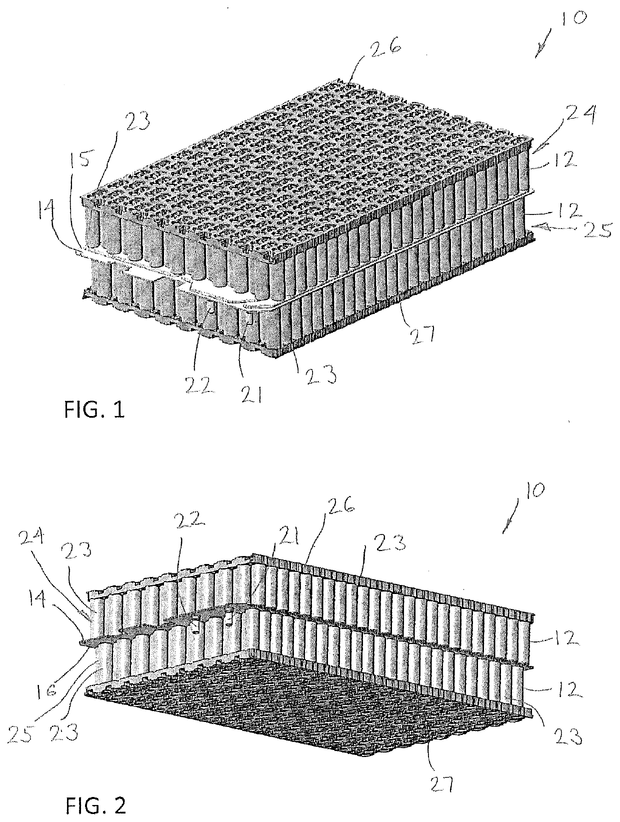
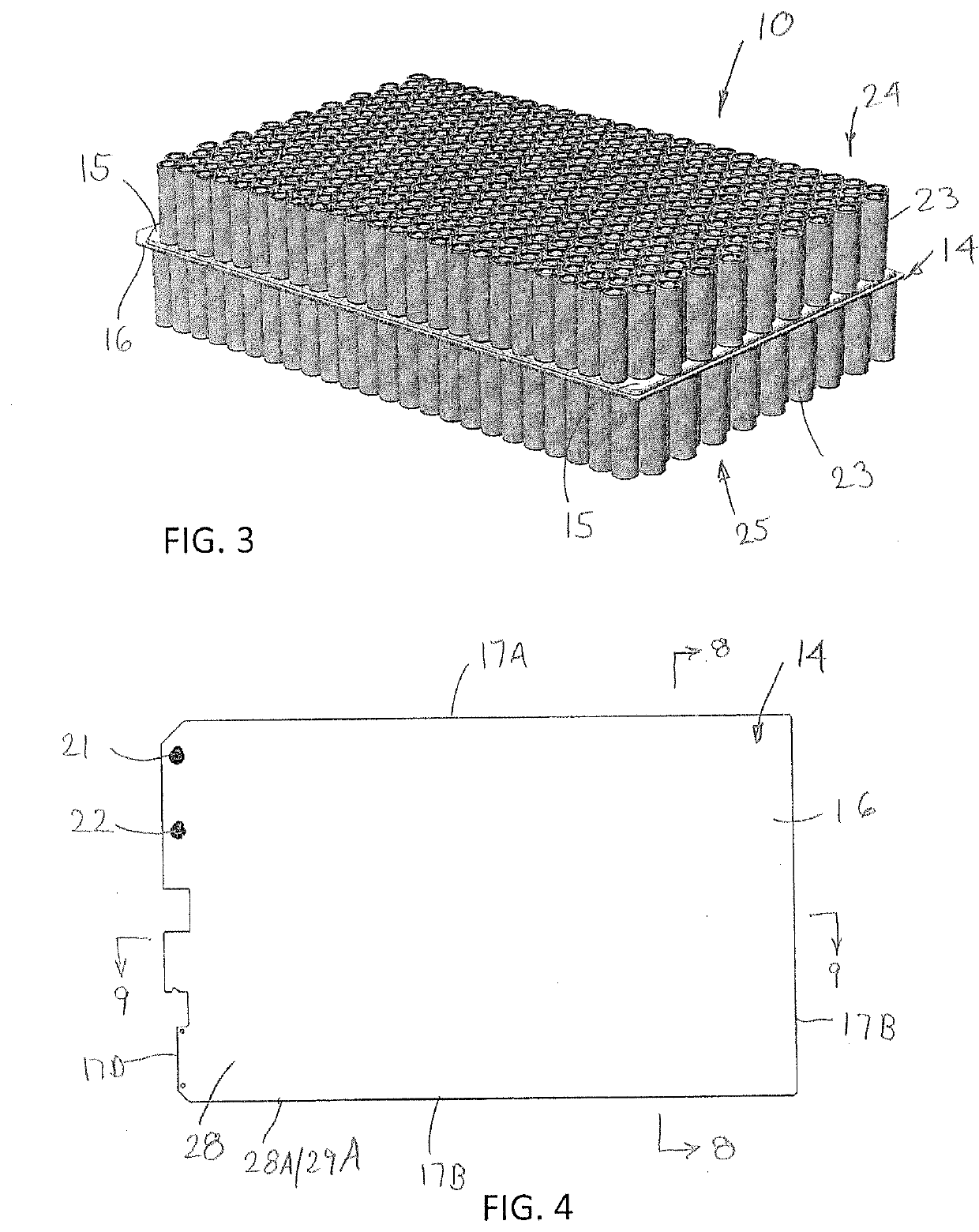
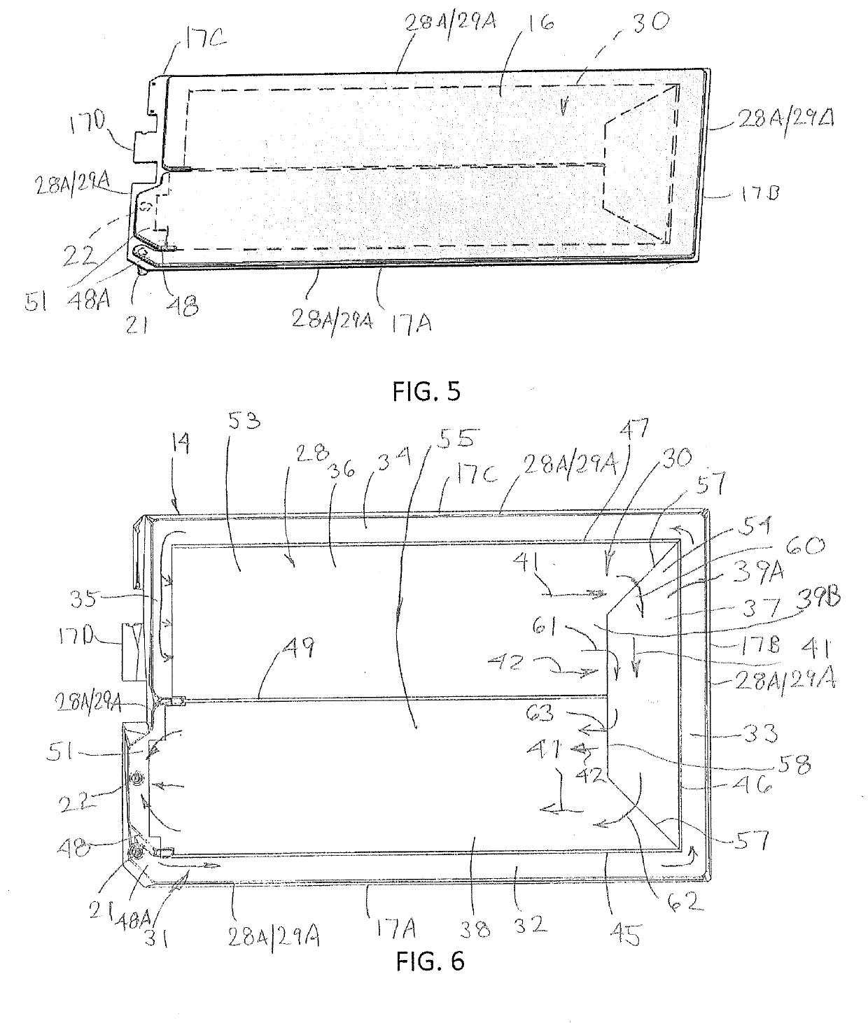
The invention is about a new battery module or battery pack with improved heat dissipation from individual battery cells. An improved cold plate is also included, which provides a more uniform temperature gradient across the entire cooling surfaces of the cold plate for better heat transfer from the battery cells to the coolant. The cold plate has multiple channel sections that form a serpentine counter flow path through the cold plate, which leads to more even heat removal from the battery cells for better performance and longer lifespan. The cooling channel includes turbulators or fins to increase heat transfer between the cooling surfaces and the coolant such that each surface is cooled more evenly. The invention also includes an improved flow of coolant with reduced temperature differences between the warmest and coolest areas of the cold plate. This arrangement further improves the temperature gradient over the cooling surfaces for better battery performance.

Problems solved by technology

During operation, the charge and discharge of the battery cells can generate heat, which in excess can negatively affect battery performance and lifespan.

Method used


Image

  • Serpentine counter flow cold plate for a vehicle battery module
  • Serpentine counter flow cold plate for a vehicle battery module
  • Serpentine counter flow cold plate for a vehicle battery module

Examples


second embodiment

[0046]In an alternative embodiment as seen in FIG. 11, the above-described construction may be modified to form a cold plate 70 which is reconfigured to rearrange the pattern of the paths of a coolant channel 71. In view of the detailed discussion above, further discussion of the specific features of the cold plate 70 is not required. As diagrammatically shown, the cold plate 70 includes an inlet port 72 and outlet port 73.

[0047]Here again, a multi-path interior coolant channel 71 is provided extending between the inlet port 72 and outlet port 73 to absorb heat from the cooling surfaces, which are formed the same as cooling surfaces 15 and 16. The coolant channel 71 is formed in a multi-path pattern defined by multiple channel sections 74-79 that flow one into the other to form a second variation of a serpentine counter flow pattern through the interior chamber 80 of the cold plate 70.

[0048]To form the channel sections 74-79 and generate turbulent flow within portions of the coolant...

third embodiment

[0054]Next, FIG. 12 is a bottom perspective view as viewed from the side of the cold plate 100 of the present invention, wherein FIG. 13 is a bottom cross-sectional view of the cold plate 100 which diagrammatically illustrates the location of the inlet and outlets in phantom outline. In view of the detailed discussion above, further discussion of the specific features of the cold plate 100 is not required.

[0055]Generally, the cold plate 100 includes an inlet 102 and outlet 103. In this configuration of the cold plate 100, the cold plate 100 includes the same arrangement as described above relative to cold plate 14. Here again, a multi-path interior coolant channel 104 is provided extending between the inlet 102 and 103 to absorb heat from the cooling surfaces formed the same as cooling surfaces 15 and 16. The coolant channel 104 is formed in a multi-path pattern defined by multiple channel sections 105-111 that flow one into the other to form the same serpentine counter flow pattern...


PUM


Abstract

A battery module or battery pack is provided having a serpentine counter flow cold plate with improved dissipation of heat from individual battery cells, wherein the cold plate provides a more uniform temperature gradient across the cold plate to more evenly transfer heat from the battery cells to liquid coolant circulating through the cold plate. The cold plate selectively omits turbulator material upstream of turbulators to control and govern the coolant fed into and through the turbulators to provide a more uniform temperature gradient across the cooling surfaces.

Description

CROSS REFERENCE TO RELATED APPLICATIONS[0001]This application claims priority of U.S. Provisional Patent Application 62 / 767,224, filed Nov. 14, 2018, the disclosure of which is incorporated herein by reference in its entirety.FIELD OF THE INVENTION[0002]The invention relates to a vehicle battery module or battery pack having multiple battery cells, and more particularly to a cold plate for cooling the battery cells during operation.BACKGROUND OF THE INVENTION[0003]Electric vehicles are typically powered by at least one battery module or battery pack, which incorporates a plurality of battery cells disposed one adjacent to the other. During operation, the charge and discharge of the battery cells can generate heat, which in excess can negatively affect battery performance and lifespan. As such, known battery modules may include cooling devices to transfer and dissipate heat from the battery cells to maintain a stable operating temperature for the batteries. Such cooling devices inclu...

Claims


Application Information

Patent Timeline
IPC IPC(8): H01M10/6568B60L58/26H01M10/6555H01M10/625H01M10/613
CPCH01M10/6568H01M10/613H01M10/6555H01M10/625B60L58/26H01M10/617H01M10/6557H01M2220/20F28D1/035F28D9/0056F28F3/12F28F3/027Y02T10/70Y02E60/10
Inventor COLLINS, TYLER
Owner RIVIAN IP HLDG LLC
Learn More