Engineering operation machine

A working machine and engineering technology, applied in mechanical equipment, fluid pressure actuation devices, fluid pressure actuation system components, etc., can solve the problems of wasting energy, reducing the overall energy efficiency of the system, affecting the service life of the hydraulic system, etc.

Active Publication Date: 2016-03-30
TAIYUAN UNIV OF TECH
View PDF6 Cites 4 Cited by
  • Summary
  • Abstract
  • Description
  • Claims
  • Application Information

AI Technical Summary

Problems solved by technology

[0002] Construction machinery is driven by hydraulic cylinders. Among the mechanical devices that require the working device to reciprocate frequently up and down, usually due to the heavy weight of the working device itself, when the hydraulic cylinder drives it up, the hydraulic system needs to overcome its gravity to work. When the working device is lowered, the work The potential energy of the device is converted into heat energy through the throttling of the hydraulic valve, which not only wastes energy, but also increases the oil temperature of the hydraulic system, increases the probability of system failure, and affects the service life of the hydraulic system
[0003] For this reason, the hydraulic system is usually equipped with a cooler to reduce the temperature, but the work of the cooler requires a special cooling system, which consumes extra energy and reduces the overall energy efficiency of the system
Especially for large-scale hydraulic systems, the system flow is large, the energy loss caused by throttling is greater, and the resulting system heating will be more serious, so large-scale hydraulic systems usually require an independent high-power cooling system to meet the system temperature control requirements. The overall energy efficiency of the system is further reduced

Method used


Image

  • Engineering operation machine
  • Engineering operation machine
  • Engineering operation machine

Examples


Embodiment 1

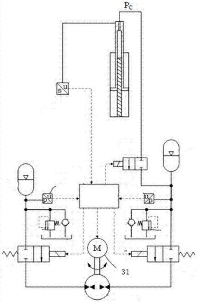
[0084] Embodiment 1: The difference between this embodiment and the existing hoisting machine is that the luffing hydraulic cylinder is a hydraulic cylinder with three cavities: an extension cavity, a retraction cavity and a recovery cavity, and the telescopic hydraulic cylinder has an extension cavity, a retraction cavity Hydraulic cylinder with three cavities of return cavity and recovery cavity ( image 3 shown).

[0085] The cylinder body of the luffing hydraulic cylinder is connected to the vehicle frame through a pin shaft, and the piston rod of the luffing hydraulic cylinder is connected to the main arm through a pin shaft. The cylinder body of the telescopic hydraulic cylinder is connected to the main arm through a pin shaft, and the piston rod of the telescopic hydraulic cylinder is connected to the telescopic arm through a pin shaft.

[0086] The luffing hydraulic cylinder is connected with the luffing recovery hydraulic system, and the telescopic hydraulic cylinder...

Embodiment 2

[0129] Embodiment 2: The difference between this embodiment and the existing hydraulic shovel lies in the hydraulic cylinder and the hydraulic cylinder drive system.

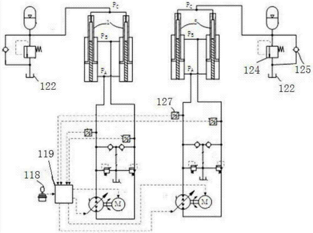
[0130] The two boom hydraulic cylinders and the two stick hydraulic cylinders are hydraulic cylinders with three cavities. The third working oil port P of the two boom hydraulic cylinders C The oil port is connected with the high pressure accumulator.

[0131] The oil port of the high-pressure accumulator is respectively connected to the high-pressure side of the safety valve 124 and the one-way valve 125, and the low-pressure side of the safety valve and the one-way valve are both connected to the oil tank. The permissible direction of oil flow is from the tank to the high pressure accumulator.

[0132] The boom hydraulic cylinder driving system includes a joystick 118 , a first controller 119 , a hydraulic pump motor, a prime mover, an oil tank 122 , a safety valve 124 , a one-way valve 125 and two pressure ...

Embodiment 3

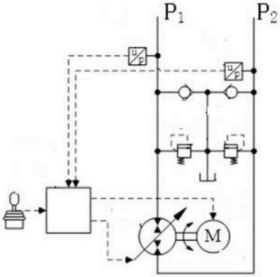
[0153] Example 3: Figure 13 As shown, the difference between this embodiment and the existing loader is that the boom hydraulic cylinder is a hydraulic cylinder with three cavities, the dump bucket hydraulic cylinder is a hydraulic cylinder with three cavities, and the recovery chamber of the boom hydraulic cylinder is connected to Boom recovery hydraulic system, the recovery cavity of the dump bucket hydraulic cylinder is connected to the dump bucket recovery hydraulic system. Boom recovery hydraulic system and tipping bucket recovery hydraulic system have the same structure, including: proportional valve, balance accumulator, balance chamber overflow valve, balance chamber pressure sensor, balance chamber oil supply valve, balance chamber solenoid valve, quantitative pump, Servo motor, surge chamber solenoid valve, surge accumulator, surge chamber overflow valve, surge chamber pressure sensor, surge chamber filling valve, recovery controller. Among them, the boom recovery ...


PUM


Abstract

The invention relates to an engineering operation machine and belongs to the field of machines. The engineering operation machine comprises a hydraulic cooling system, a liquid-gas energy storage balance system, a hydraulic cylinder driving system and a working device driving system. The hydraulic cooling system comprises a hydraulic system, a cooler, a cooling control device, an oil tank and a heat recovery device. The heat recovery device comprises a heat exchanger, a working medium pump, a working medium filter, a working medium storage device, a condenser, a condenser control device, an electric generator, an expander, a heat recovery controller and an electricity storage device. The hydraulic system sucks hydraulic oil from the oil tank through an oil suction opening, the hydraulic oil enters the heat recovery device through an oil return opening after work is completed, the hydraulic oil subjected to heat exchange through the heat recovery device enters the cooler to be cooled, the hydraulic oil returns to the oil tank finally, and circulating is completed. According to the engineering operation machine, the potential energy of a working device can be recovered effectively, stored energy is released in the ascending process of the working device, and thus energy is saved. The cooling power of the cooling system can be reduced, and the non-load operation energy consumption of the cooling system is reduced when the system temperature is low.

Description

technical field [0001] The process machinery described in the present invention includes excavators, shovels, forklifts, hoists, and loaders. Background technique [0002] Construction machinery is driven by hydraulic cylinders. Among the mechanical devices that require the working device to reciprocate frequently up and down, usually due to the heavy weight of the working device itself, when the hydraulic cylinder drives it up, the hydraulic system needs to overcome its gravity to work. When the working device is lowered, the work The potential energy of the device is converted into heat energy through the throttling of the hydraulic valve, which not only wastes energy, but also increases the oil temperature of the hydraulic system, increases the probability of system failure, and affects the service life of the hydraulic system. [0003] For this reason, the hydraulic system is usually equipped with a cooler to reduce the temperature, but the work of the cooler requires a ...

Claims


Application Information

Patent Timeline
Patent Type & Authority Applications(China)
IPC IPC(8): F15B21/08F15B21/04
CPCF15B21/042F15B21/08
Inventor 权龙董致新杨晋黄伟男黄家海蓝媛葛磊
Owner TAIYUAN UNIV OF TECH
Why Eureka
Try Eureka