
Low profile zero/low insertion force package top side flex cable connector architecture

a technology of flex cable connectors and low-profiles, which is applied in the direction of cable terminations, fixed connections, coupling device connections, etc., can solve the problems of signal degradation and loss along this path, high-speed signals are especially susceptible to signal degradation and loss, and it is difficult to recover the signal correctly at the destination

Active Publication Date: 2014-08-07
INTEL CORP
View PDF10 Cites 48 Cited by
  • Summary
  • Abstract
  • Description
  • Claims
  • Application Information

AI Technical Summary

Benefits of technology

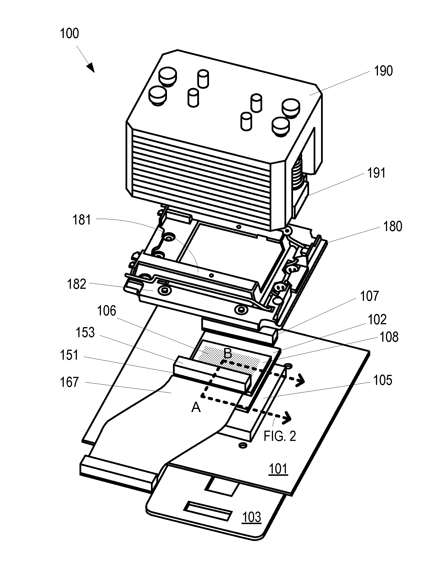
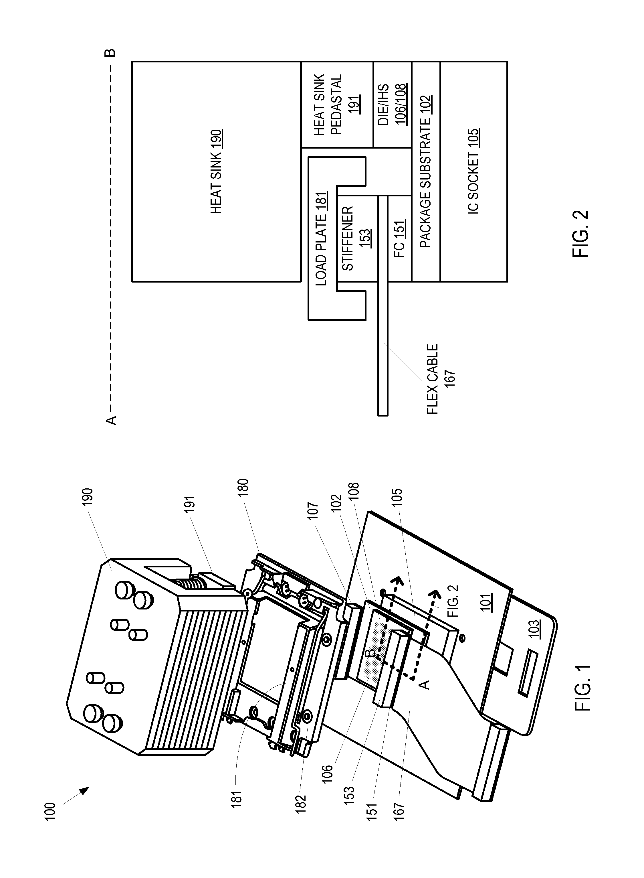
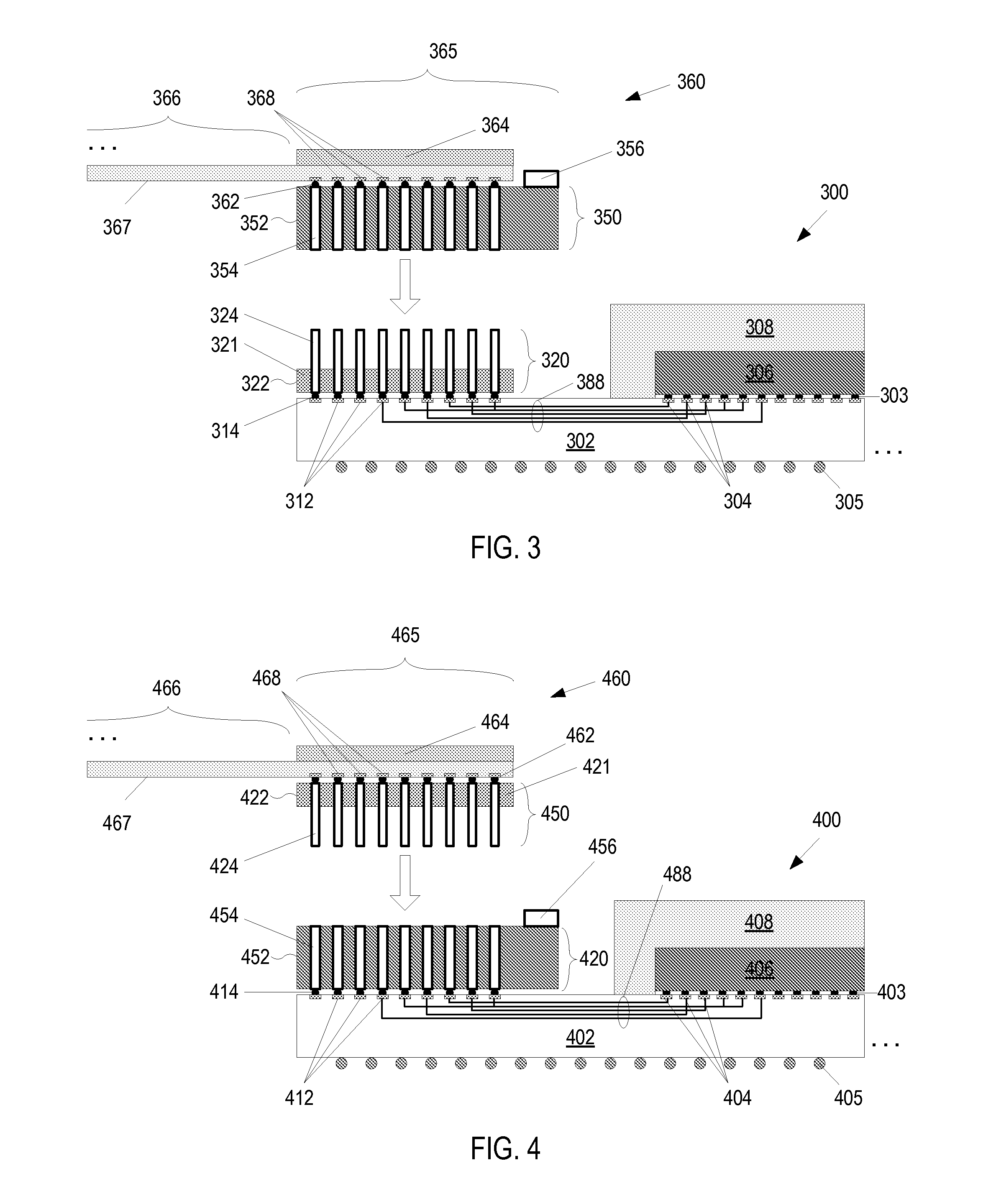
The present invention provides an integrated circuit package with a flex cable receptacle that connects to a flex cable through a zero or low insertion force connector without requiring a complex compressive loading mechanism. This reduces the overall height of the integrated circuit package assembly and enables low-profile and thin-formed system designs. The invention also addresses signal degradation and losses caused by high-speed signals and provides better performance and reliability for high-speed signals.

Problems solved by technology

However, signals along this path are susceptible to signal degradation and losses due to parasitics, transmission and return losses, and cross talks.
The signal degradation and losses along this path are especially pronounced for high speed signals.
For high speed signals, an interconnect path through two sockets and a PCB may degrade the signal enough to cause difficulty in recovering the signal correctly at the destination due to the transmission losses.
However, even with better composite materials, significant transmission losses may still be occur for longer interconnect paths and at higher signaling rates.

Method used


Image

  • Low profile zero/low insertion force package top side flex cable connector architecture
  • Low profile zero/low insertion force package top side flex cable connector architecture
  • Low profile zero/low insertion force package top side flex cable connector architecture

Examples


Embodiment Construction

[0016]The following description sets forth numerous specific details such as examples of specific systems, components, methods, and so forth, in order to provide a good understanding of several embodiments of the present invention. It will be apparent to one skilled in the art, however, that at least some embodiments of the present invention may be practiced without these specific details. In other instances, well-known components or methods are not described in detail or are presented in a simple block diagram format in order to avoid unnecessarily obscuring the present invention. Thus, the specific details set forth are merely exemplary. Particular implementations may vary from these exemplary details and still be contemplated to be within the spirit and scope of the present invention.

[0017]Reference in the description to “one embodiment” or “an embodiment” means that a particular feature, structure, or characteristic described in connection with the embodiment is included in at l...


PUM


Abstract

An integrated circuit package is presented. In an embodiment, the integrated circuit package has contact pads formed on the top side of a package substrate, a die electrically attached to the contact pads, and input / output (I / O) pads formed on the top side of the package substrate. The I / O pads are electrically connected to the contact pads. The integrated circuit package also includes a flex cable receptacle electrically connected to the I / O pads on the top side of the package substrate. The flex cable receptacle is non-compressively attachable to a flex cable connector and includes receptacle connection pins electrically connected to the I / O pads.

Description

FIELD OF THE INVENTION[0001]This invention relates generally to an integrated circuit package. More specifically, this invention relates to an integrated circuit package for connecting to a high speed input / output (I / O) flex cable.BACKGROUNDS AND RELATED ARTS[0002]One way of interconnecting signals from one integrated circuit device to another integrated circuit device is to route the signals through the package substrate of one device down to a device socket, onto a motherboard such as a printed circuit board (PCB), and through another device socket up the package substrate of the other device. However, signals along this path are susceptible to signal degradation and losses due to parasitics, transmission and return losses, and cross talks. The signal degradation and losses along this path are especially pronounced for high speed signals. For high speed signals, an interconnect path through two sockets and a PCB may degrade the signal enough to cause difficulty in recovering the s...

Claims


Application Information

Patent Timeline
IPC IPC(8): H01L23/00H01B7/04
CPCH01B7/04H01L24/72H01R12/62H05K1/142H05K1/147H05K3/361H05K2201/10318H05K2201/10325H05K2201/10424H05K2201/10674H05K2201/2009H01L23/49811H01L2224/16H01L2924/15192H01L2924/15311H01L2224/16227H01L2224/16225H01L2924/00014H01L2224/0401H01L23/3675H01L23/49838H01L24/17H01L2924/14H01R12/79H05K2201/10681
Inventor GANESAN, SANKAVISWANATH, RAM S.
Owner INTEL CORP
Learn More