

Image processing method, image processing apparatus, non-transitory computer-readable medium, and image-pickup apparatus
a technology of image processing and image, which is applied in the direction of color television details, television systems, instruments, etc., can solve the problem that the brightness cannot be well reproduced in an area of brightness
- Summary
- Abstract
- Description
- Claims
- Application Information
AI Technical Summary
Benefits of technology
Problems solved by technology
Method used
Image

Examples
first embodiment
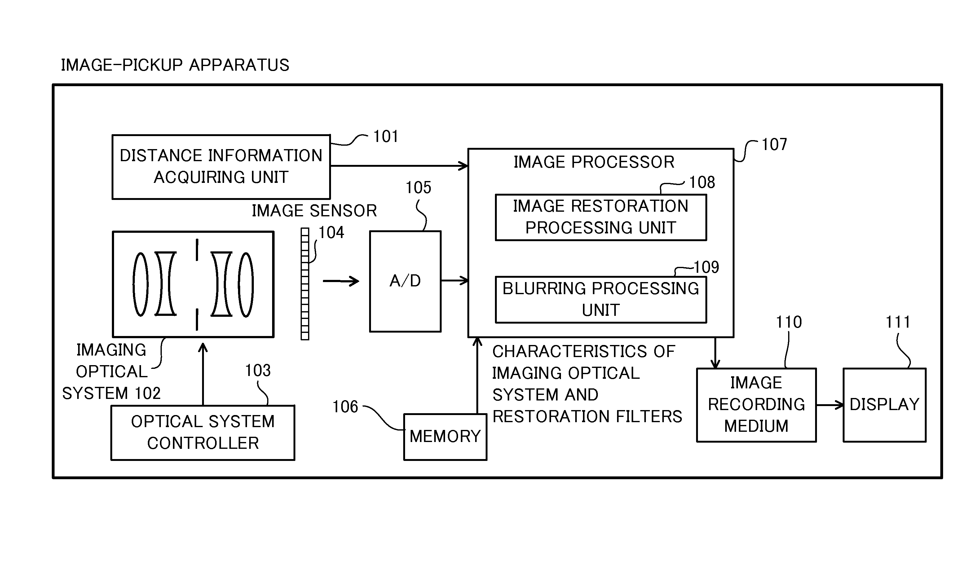
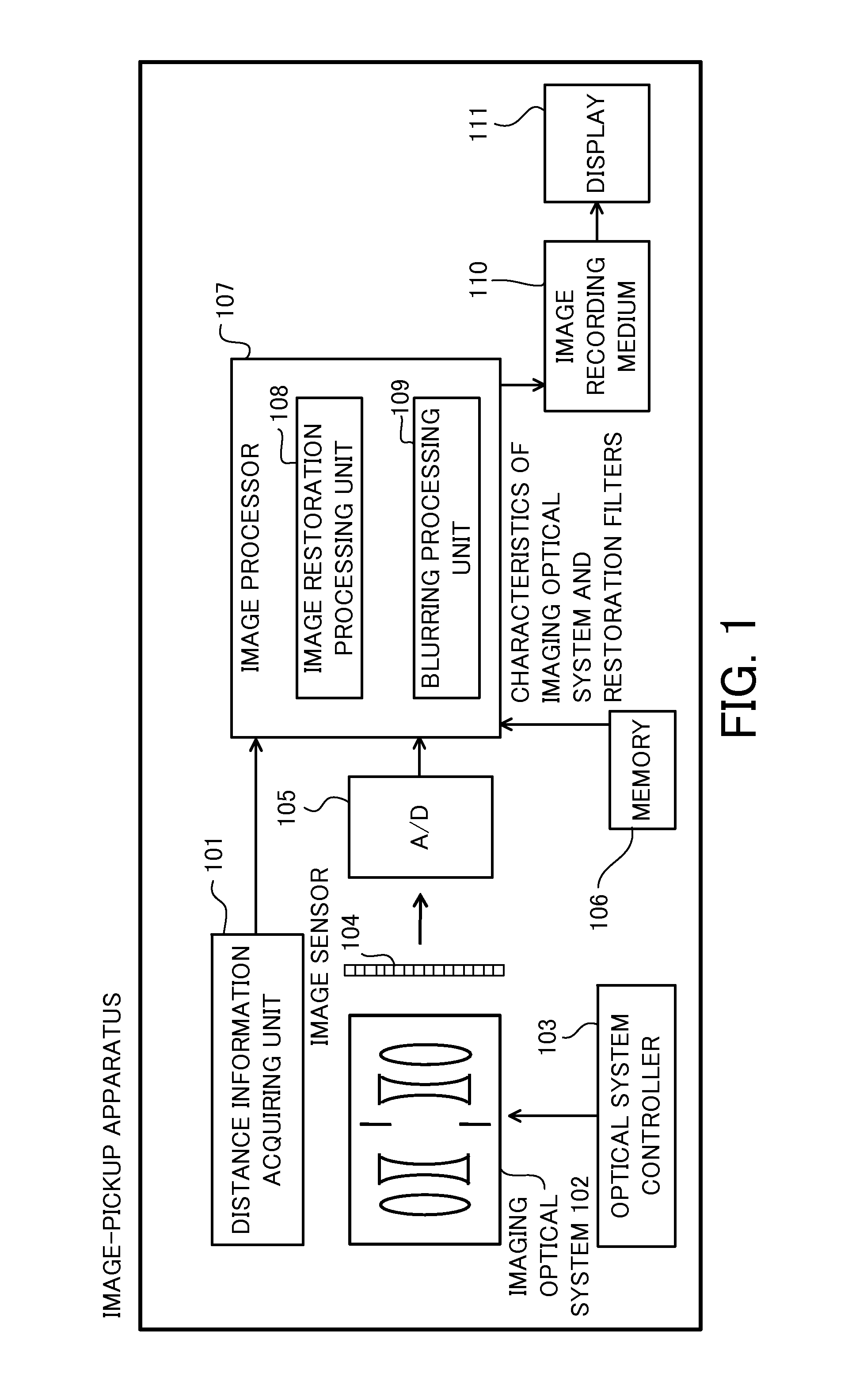
[0034]FIG. 1 is a block diagram of a principal part of an image-pickup apparatus according to a first embodiment. The image-pickup apparatus may be a compact digital camera, a single-lens reflex camera, a mirror-less camera or a digital video camera.
[0035]The image-pickup apparatus includes a distance information acquiring unit 101, an imaging optical system (image-pickup optical system) 102, an optical system controller 103, an image sensor 104, an A / D converter 105, a memory 106, an image processor 107, an image recording medium 110, and a display device 111. A controller (not illustrated) controls each of the above components, and can be implemented as a micro computer.
[0036]The distance information acquiring unit 101 acquires distance information between the image-pickup apparatus and each object. A method of acquiring the distance information is not specifically limited. For example, information on a plurality of parallax images may be acquired by a compound eye of a stereo cam...
second embodiment
[0098]FIG. 10 is a block diagram of a principal part of an image-pickup apparatus according to a second embodiment. The image-pickup apparatus according to this embodiment does not include the distance information acquiring unit 101, but includes an image processor 205 instead of the image processor 107 and a memory 213 instead of the memory 106. The image-pickup apparatus of this embodiment further includes an exposure controller 212. This embodiment defines an exposure amount as a light amount which the image sensor 104 receives. In this embodiment, “images having different exposure amounts” mean images captured with a different condition of at least one of the shutter speed, F value, and the ISO sensitivity.
[0099]The exposure controller 212 controls the exposure amount. The memory 213 stores information on images obtained by capturing the same object a plurality of times with different exposure amounts and information on the exposure amounts corresponding to the plurality of capt...
third embodiment
[0115]FIG. 14 is a block diagram of an image processing system according to a third embodiment. The image processing system includes a recording medium 301, an image-pickup apparatus 302, an image processing apparatus 303, a display device 311, and an output device 309.
[0116]The recording medium 301 may be a semiconductor memory, a hard disk, or a server on a network, for example.
[0117]The image-pickup apparatus 302 includes the imaging optical system and the image sensor, and also includes the distance information acquiring unit 101 illustrated in FIG. 1.
[0118]The image processing apparatus 303 is a computer configured to perform the shaping processing and the blurring processing, and includes a controller (not illustrated). The image processing apparatus 303 may be composed of a server connected with the image-pickup apparatus 302 via the Internet (cloud computing). Of course, the image processing apparatus 303 may be connected via a network to another personal computer (“PC”), a ...
PUM
 Abstract
Description
Claims
Application Information