Eureka AIR delivers breakthrough ideas for toughest innovation challenges, trusted by R&D personnel around the world.

Planar lighting device

Inactive Publication Date: 2014-08-07
NAT CENT UNIV
View PDF19 Cites 2 Cited by
  • Summary
  • Abstract
  • Description
  • Claims
  • Application Information

AI Technical Summary

Benefits of technology

The patent describes a planar lighting device with a light guide plate and a side-emitting lighting module. The side-emitting lighting module is embedded in the light guide plate and emits light towards the side surface of the light guide plate. The light is then guided by the light guide plate and emerges from the light emission surface of the light guide plate. The device can have reflective layers on the sides facing the light emission surface and the back light surface, and microstructures such as pyramid or lens array can be used to enhance the lighting effect. A bump with reflective surfaces can also be used for interference reduction. The lighting device can be used with different light-emitting diodes and a wavelength conversion layer can be added for better color rendering. Technical effects of the patent include improved lighting effect, reduced interference, and improved color rendering.

Problems solved by technology

However, because of limitations in the normal light intensity of the light emitted from the light emitting element of the direct-type back light module, the brightness of the direct-type back light module may be non-uniform.
However, such a diffuser may increase the thickness of the direct-type back light module.
However, the edge-type back light module is not suitable for a back light source used in a large display panel since the brightness of the light guide plate is decreased as a lateral distance of the light guide plate from the light emitting element is increased.
In addition, the refractive index of the light emitting element disposed in the air is unmatched to the light guide plate which can cause Fresnel reflection, thereby leading to a reduction in the optical coupling efficiency of the light emitting module to the light guide plate, and a loss in the overall light energy.

Method used


Image

  • Planar lighting device
  • Planar lighting device
  • Planar lighting device

Examples


Embodiment Construction

[0025]In the following detailed description, for purposes of explanation, numerous specific details are set forth in order to provide a thorough understanding of the disclosed embodiments. It will be apparent, however, that one or more embodiments may be practiced without these specific details. In other instances, well-known structures and devices are schematically depicted in order to simplify the drawings.

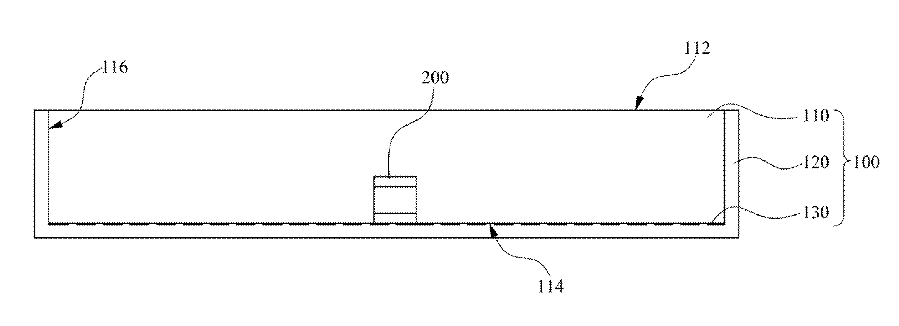
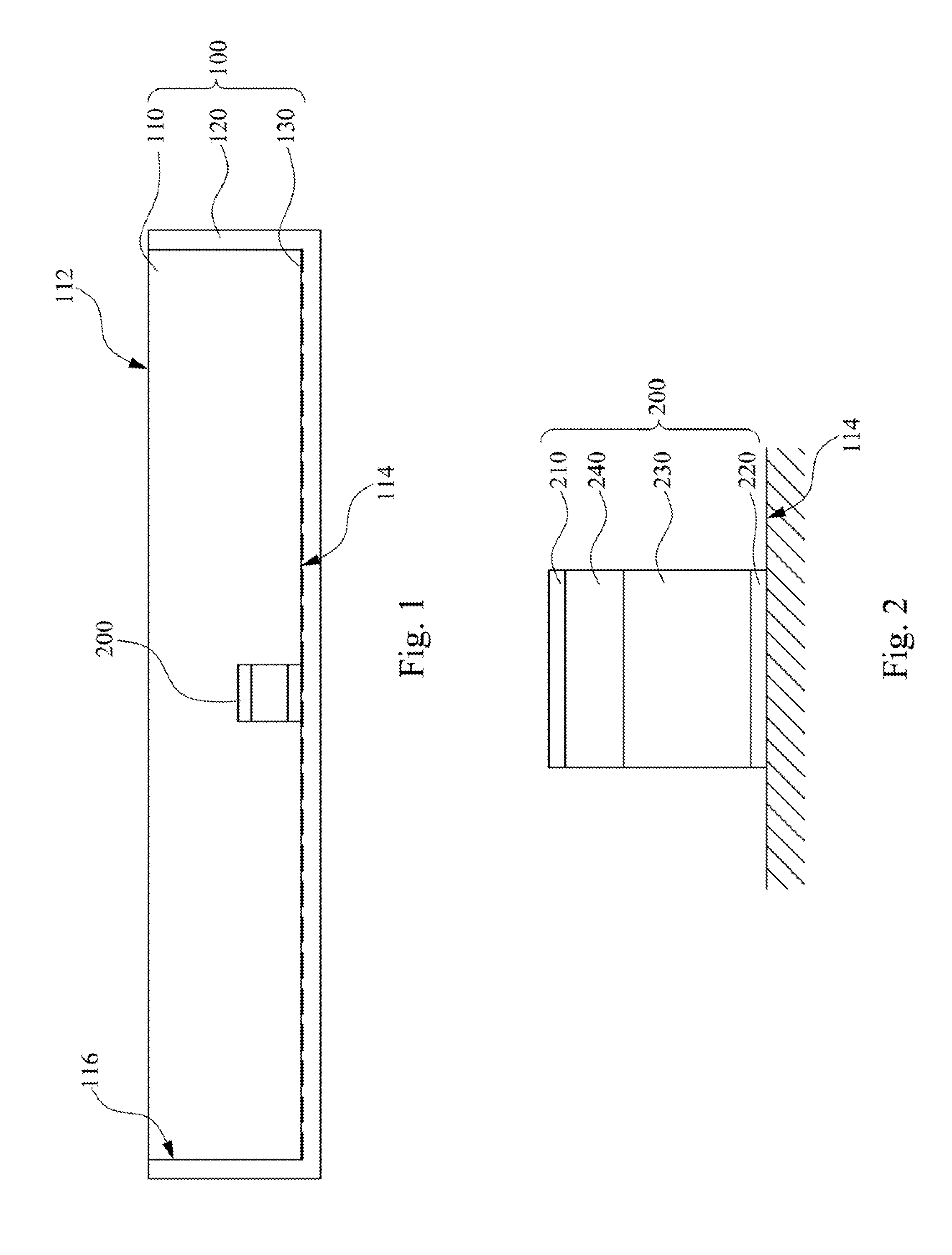
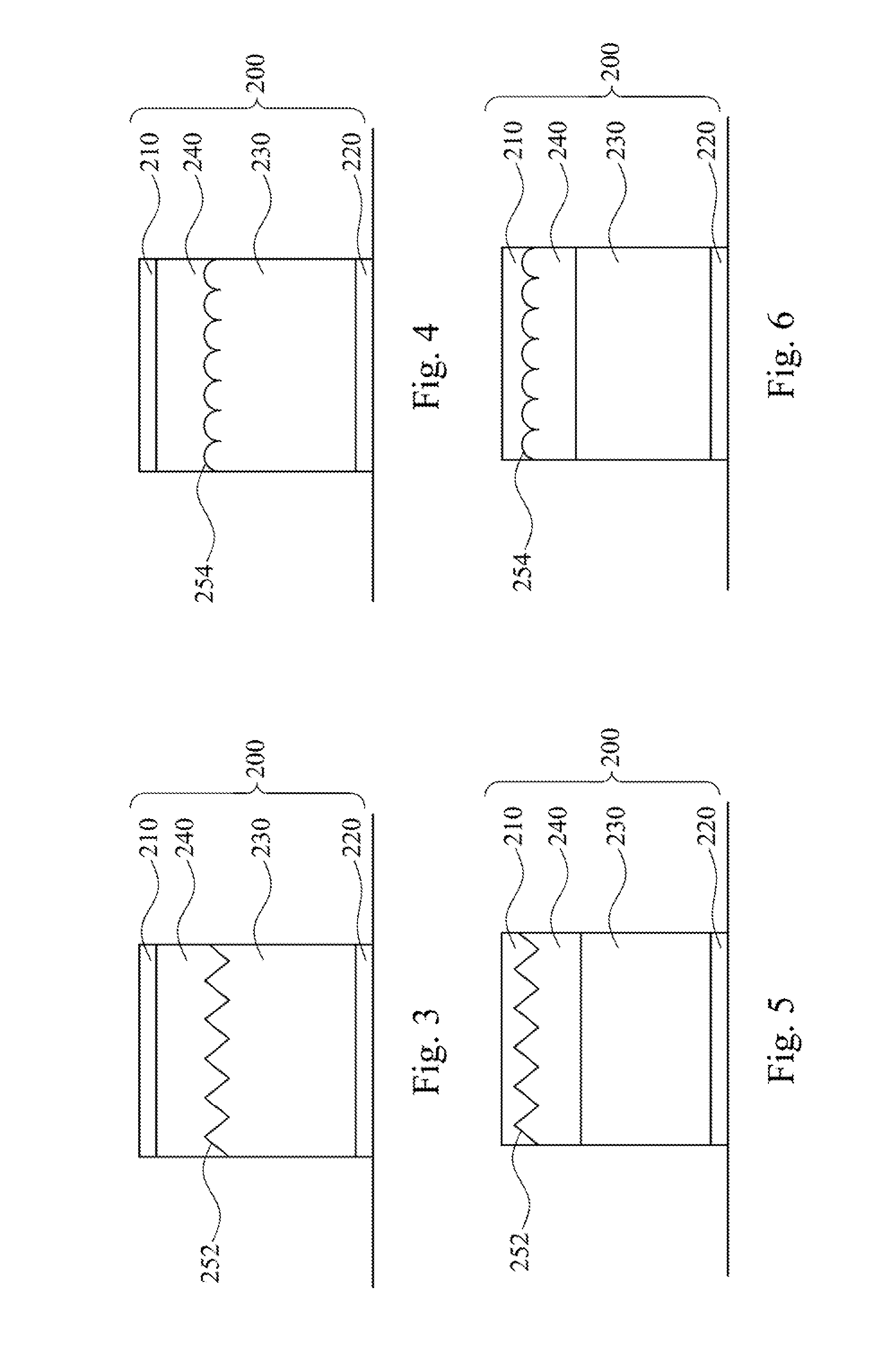
[0026]FIG. 1 is a schematic diagram of a planar lighting device according to a first embodiment of the present invention. The planar lighting device includes a light guide plate 100 and a side-emitting lighting module 200. The light guide plate 100 has a light emission surface 112 a back light surface 114, and at least one side surface 116. The back light surface 114 is opposite to the light emission surface 112, and the side surface 116 extends between the light emission surface 112 and the back light surface 114. The side-emitting lighting module 200 is embedded into the light...


PUM


Abstract

A planar lighting device includes a light guide plate and a side-emitting lighting module. The light guide plate includes a light emission surface, a back light surface, and at least one side surface. The back light surface is opposite to the light emission surface, and the side surface extends between the light emission surface and the back light surface. The side-emitting lighting module is embedded into the light guide plate, such that the side-emitting lighting module emits light toward the side surface of the light guide plate. The light is then guided by the light guide plate and emerges from the light emission surface of the light guide plate.

Description

RELATED APPLICATIONS[0001]This application claims priority to Taiwanese Application Serial Number 102104427, filed Feb. 5, 2013, which is herein incorporated by reference.BACKGROUND[0002]1. Technical Field[0003]The present disclosure relates to a planar lighting device.[0004]2. Description of Related Art[0005]A back light source of a typical display panel can employ a direct-type back light module or an edge-type back light module. A light emitting element of the direct-type back light module is disposed below a light emission surface of the direct-type back light module, and light can emerge from right beneath the light emission surface. The direct-type back light module not only has a simple structure, but also can be employed in a large back light source. However, because of limitations in the normal light intensity of the light emitted from the light emitting element of the direct-type back light module, the brightness of the direct-type back light module may be non-uniform. The...

Claims


Application Information

Patent Timeline
IPC IPC(8): F21V8/00
CPCG02B6/0011G02B6/0021
Inventor SUN, CHING-CHERNGWU, CHI-SHOU
Owner NAT CENT UNIV
Why Eureka
Eureka Blog
Learn More