Non-contact temperature monitoring device

a temperature monitoring and non-contact technology, applied in the direction of heat measurement, optical radiation measurement, instruments, etc., can solve the problems of difficult maintenance of non-contact temperature detectors, high frequency of electric component damage and fire occurrence, etc., to achieve more quick and accurate action, simplified operation, and accurate grasp

Inactive Publication Date: 2014-08-07
RYOU DEOG BONG
View PDF37 Cites 9 Cited by
  • Summary
  • Abstract
  • Description
  • Claims
  • Application Information

AI Technical Summary

Benefits of technology

[0025]According to the present invention, by detecting a temperature of a temperature detection object with a non-contact method while photographing the temperature detection object and by enabling to simultaneously output temperature data and image data to a monitoring unit, a temperature state and a field situation of the temperature detection object can be monitored in real time.
[0026]Further, only when an abnormal situation occurs in a temperature state of a temperature detection object, by enabling to photograph a state of the temperature detection object through an image photographing unit, operation can be simplified in a normal state, and in a urgent situation, a field situation can be more accurately grasped through image information and thus by taking a more quick and accurate action, a fire accident in an industrial field can be previously prevented.
[0027]Further, a temperature of a temperature detection area of a relatively wide size can be detected through a structure of a camera method, and by setting only a specific point within a temperature detection area, a temperature of a temperature detection object can be more stably and efficiently measured and monitored through a non-contact temperature detection unit of a simple structure that can simultaneously detect a temperature of a plurality of specific points.

Problems solved by technology

Particularly, in an industry field, in an electric component that supplies a large amount of electricity, due to heat generation, the frequency of electric component damage and fire occurrence is very high, and in this case, operation of a production facility is stopped or due to a fire, large damage may occur and thus in an industry field, a temperature monitoring device of such an electric component is essential.
When using a plurality of infrared ray sensors, an installation work thereof is difficult and a plurality of electric wires should be connected and thus such a non-contact temperature detector has a complicated structure and maintenance thereof is difficult.
Further, because a thermal image camera visually provides a relative temperature distribution of a photographing entire area, it is difficult to instantaneously grasp temperature information of a specific point, and due to a structure that cannot detect a temperature by designating only a specific point, a temperature is detected in an entire area including an unnecessary area and thus it is very inefficient in view of efficiency and a cost is expensive and thus there is a problem that the non-contact temperature detector is not widely applied in an industry field.
Particularly, because a temperature monitoring device of the conventional art simply detects only a temperature, in a state in which a temperature of a temperature detection object is considerably high, a worker cannot know an actual field situation, and only when the worker directly moves to a field, the worker can grasp a field situation and thus the worker cannot directly check fire danger of the field, whereby there is a limitation in taking an appropriate prevention action in a urgent situation.

Method used


Image

  • Non-contact temperature monitoring device
  • Non-contact temperature monitoring device
  • Non-contact temperature monitoring device

Examples


Embodiment Construction

Technical Problem

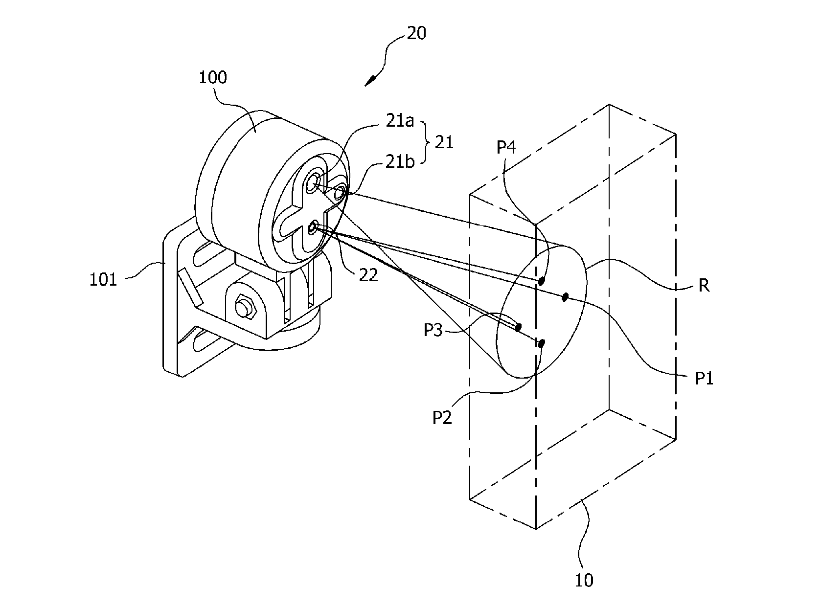
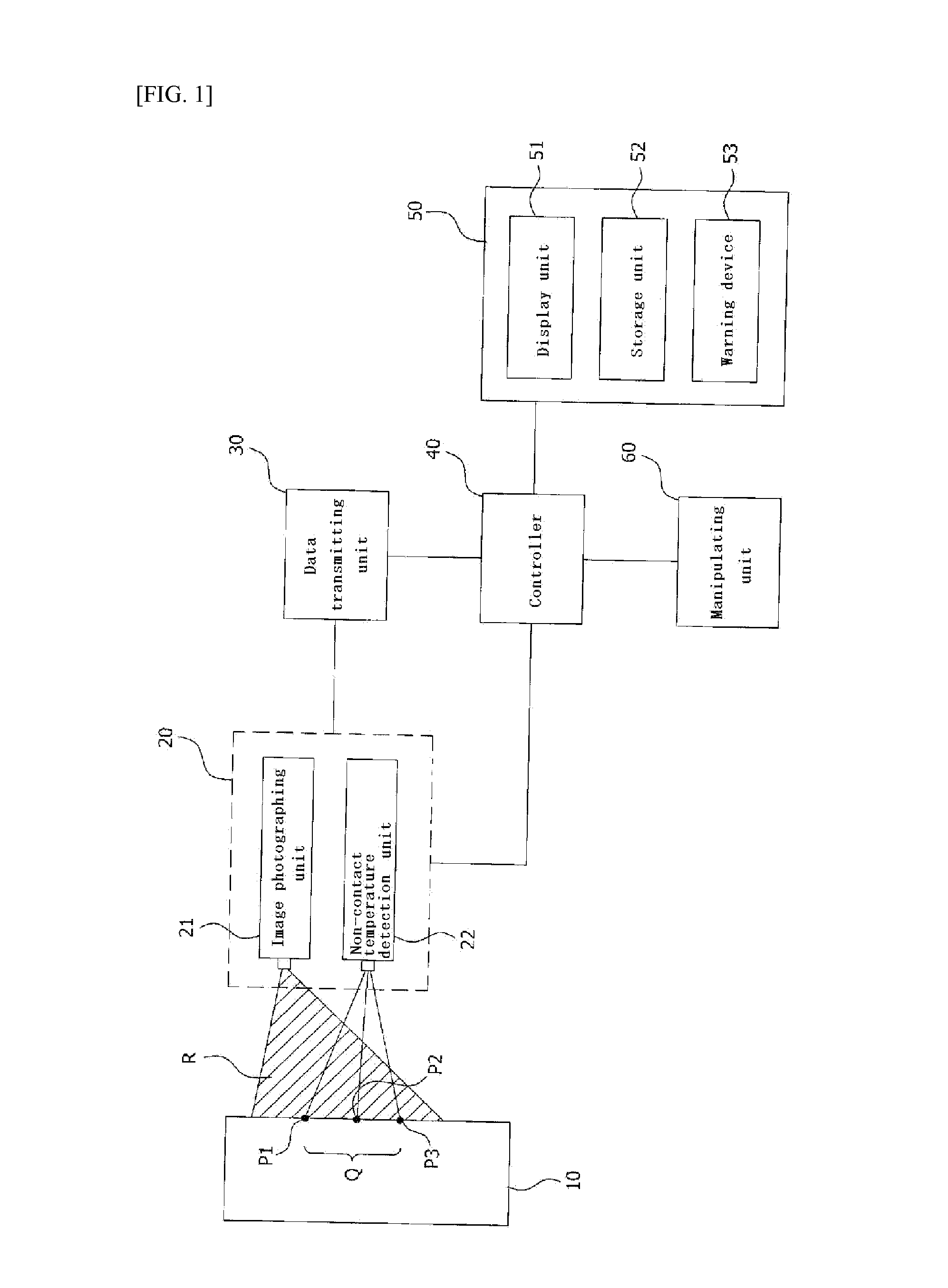
[0009]The present invention has been made in view of the above problems, and provides a non-contact temperature monitoring device that can monitor a temperature state and a field situation of a temperature detection object in real time by enabling to simultaneously output temperature data and image data to a monitoring unit by detecting a temperature of the temperature detection object with a non-contact method while photographing the temperature detection object.

[0010]The present invention further provides a non-contact temperature monitoring device that can simplify operation in a normal state by enabling to photograph a state of a temperature detection object through an image photographing unit only when an abnormal situation occurs in a temperature state of the temperature detection object and that can grasp more accurately a field situation through image information in an urgent situation and that can take thus more quick and accurate action.

[0011]The present i...


PUM

PropertyMeasurementUnit
temperatureaaaaaaaaaa
areaaaaaaaaaaa
electric resistanceaaaaaaaaaa

Abstract

The present invention pertains to a non-contact temperature monitoring device, wherein: temperature data and image data are simultaneously outputted to a monitoring unit by simultaneously photographing a temperature detection target and detecting the temperature of the temperature detection target in a non-contact manner, in which the temperature state of the temperature detection target and on-site conditions can be monitored in real time; the state of the temperature detection target is photographed using an image capturing unit only when the temperature state of the temperature detection target is abnormal, thereby simplifying an operation in a normal state and more accurately detecting on-site conditions using image information in emergency situations. Accordingly, quicker and more accurate responses are possible, thereby preventing fire accidents in industrial settings.

Description

CROSS-REFERENCE TO RELATED APPLICATION[0001]This application claims the benefit of Korean Patent Application No. 10-2011-0091407, filed on Sep. 8, 2011 in the Korean Intellectual Property Office, the disclosure of which is incorporated herein by reference.TECHNICAL FIELD[0002]The present invention relates to a non-contact temperature monitoring device. More particularly, the present invention relates to a non-contact temperature monitoring device that can monitor a temperature state and a field situation of a temperature detection object in real time by enabling to simultaneously output temperature data and image data to a monitoring unit by detecting a temperature of the temperature detection object with a non-contact method while photographing the temperature detection object and that can simplify operation in a normal state by enabling to photograph a state of a temperature detection object through an image photographing unit only when an abnormal situation occurs in a temperatur...

Claims


Application Information

Patent Timeline
Patent Type & Authority Applications(United States)
IPC IPC(8): G01K13/00
CPCG01K13/00G01J5/0066G01J5/025G01J5/026G01J5/0859G01J5/02G08B17/06G08B25/00G08C19/02
Inventor RYOU, DEOG BONG
Owner RYOU DEOG BONG
Why Eureka
Try Eureka