Polarization splitter of high polarization extinction ratio

a polarization splitter and high extinction ratio technology, applied in the field of integrated optics, can solve the problem that the polarization extinction ratio of current polarization splitters is often less than satisfactory

Inactive Publication Date: 2014-08-07
HON HAI PRECISION IND CO LTD
View PDF9 Cites 8 Cited by
  • Summary
  • Abstract
  • Description
  • Claims
  • Application Information

AI Technical Summary

Benefits of technology

The present patent relates to a polarization splitter with a relatively high polarization extinction ratio. The technical effect of the patent is to provide an improved polarization splitter that can effectively separate transverse electric wave and transverse magnetic wave, and increase the polarization extinction ratio. This is achieved by using a substrate made of birefringence crystal, such as lithium niobate, and asymmetric Y-shaped waveguide. The substrate includes a first surface with first electrodes positioned on its top surface. The Y-shaped waveguide has an input section for transmitting both transverse electric wave and transverse magnetic wave, and the first electrodes are positioned on the first surface in parallel with a central axis of the input section. The Y-shaped waveguide and the input section have an interface where the transverse magnetic wave and transverse electric wave separate. The first electrodes change the refractive index of the input section along a direction perpendicular to the central axis, which facilitates the separation of the transverse electric wave from the transverse magnetic wave and increases the polarization extinction ratio. The substrate is made of birefringence crystal, such as lithium niobate, to increase the bandwidth of the polarization splitter. The first branch and the input section lie in a common straight line, and the second branch forms an included angle with the input section. The input section, the first branch, and the second branch are made by diffusing titanium, gallium, and zinc-nickel into the first surface. The first electrodes are as long as or slightly shorter than the input section and align with it. The technical effect of the patent is to provide an improved polarization splitter with a high polarization extinction ratio.

Problems solved by technology

However, polarization extinction ratios of current polarization splitters are often less than satisfactory.

Method used


Image

  • Polarization splitter of high polarization extinction ratio
  • Polarization splitter of high polarization extinction ratio
  • Polarization splitter of high polarization extinction ratio

Examples


Embodiment Construction

[0011]Embodiments of the present disclosure will be described with reference to the drawings.

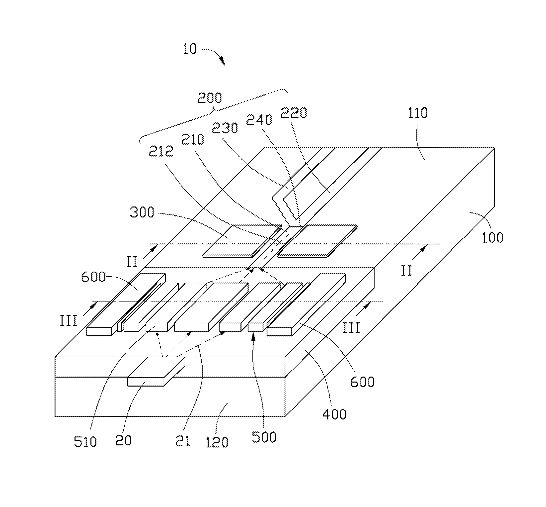
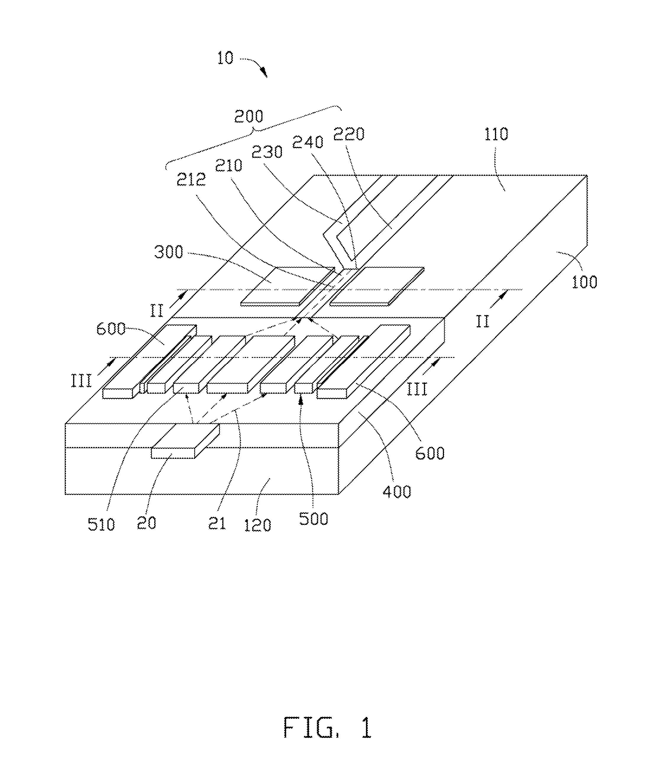
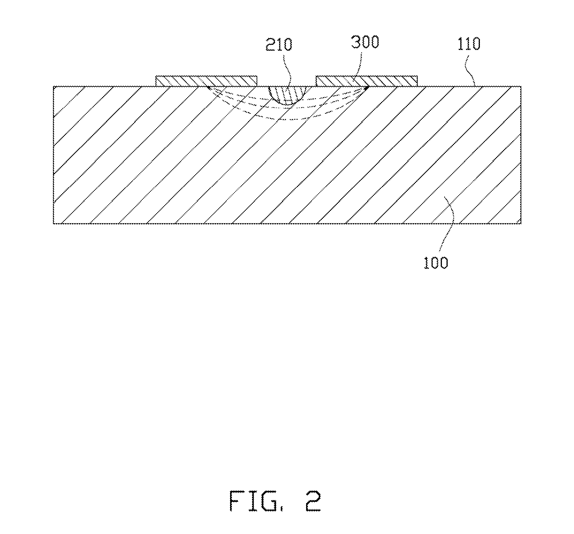
[0012]FIGS. 1 and 2 show a polarization splitter 10 according to an embodiment. The polarization splitter 10 includes a substrate 100, an asymmetric Y-shaped waveguide 200, and a pair of strip-shaped first electrodes 300. The substrate 100 is made of a birefringence crystal, such as lithium niobate, and includes a first surface 110, such as a top surface. The Y-shaped waveguide 200 is formed into the first surface 110 and includes an input section 210 for transmitting both transverse electric wave and transverse magnetic wave, a first branch 220 for only transmitting the transverse electric wave, and a second branch 230 for only transmitting the transverse magnetic wave. The first branch 220 and the second branch 230 branch off the input section 210. An interface 240 is formed between the input section 210 and the first branch 220 and the second branch 230. The first electrodes 300 are posit...


PUM


Abstract

A polarization splitter includes a substrate, an asymmetric Y-shaped waveguide, and a pair of strip-shaped electrodes. The substrate is made of a birefringence crystal and includes a surface. The Y-shaped waveguide is formed into the surface and includes an input section for transmitting both transverse electric wave and transverse magnetic wave, a first branch for only transmitting the transverse electric wave, and a second branch for only transmitting the transverse magnetic wave. The first branch and the second branch branch off the input section. The electrodes are positioned on the surface, arranged at two opposite sides of the input section and substantially parallel with a central axis of the input section.

Description

BACKGROUND[0001]1. Technical Field[0002]The present disclosure relates to integrated optics and, more particularly, to a polarization splitter having a relatively high polarization extinction ratio.[0003]2. Description of Related Art[0004]Polarization splitters are used in integrated optics to separate transverse electric wave and transverse magnetic wave. However, polarization extinction ratios of current polarization splitters are often less than satisfactory.[0005]Therefore, it is desirable to provide a polarization splitter, which can overcome the above-mentioned problem.BRIEF DESCRIPTION OF THE DRAWINGS[0006]Many aspects of the present disclosure can be better understood with reference to the following drawings. The components in the drawings are not necessarily drawn to scale, the emphasis instead being placed upon clearly illustrating the principles of the present disclosure.[0007]FIG. 1 is an isometric schematic view of a polarization splitter, according to an embodiment.[00...

Claims


Application Information

Patent Timeline
IPC IPC(8): G02B6/126
CPCG02B6/126G02F1/0136G02F1/035G02F2203/07G02B6/29344
Inventor HUANG, HSIN-SHUN
Owner HON HAI PRECISION IND CO LTD
Why Eureka
Try Eureka