Hub for a wind turbine

a technology for wind turbines and hubs, applied in the direction of propellers, propulsive elements, water-acting propulsive elements, etc., can solve the problems of reduced supply, increased production costs, and increased production costs, so as to reduce the need for manual labor, reduce the need for large parts, and reduce the cost

Active Publication Date: 2014-08-07
VESTAS WIND SYST AS
View PDF3 Cites 7 Cited by
  • Summary
  • Abstract
  • Description
  • Claims
  • Application Information

AI Technical Summary

Benefits of technology

[0022]The shell parts may be cast from a castable material. Accordingly, each of the shell parts is manufactured using a casting technique. This is an advantage, because casting is a low cost manufacturing method, and the resulting parts are relatively strong and durable.
[0023]Furthermore, since the hub comprises at least two shell parts, which are casted separately, and since the shell parts are significantly smaller than the resulting hub, it is possible to perform a more simple casting operation, to reduce the need for manual labour during the casting process, and to facilitate reuse of the sand used for forming the casting mould.
[0024]In summary, the hub of the invention is easy to handle during manufacture and transport, due to the at least two shell parts. It is manufactured using a cost effective technique, which also provides a strong and durable hub which is able to withstand the expected loads during operation.

Problems solved by technology

The large parts are difficult to handle and transport from the manufacturing facility to the operating site of the wind turbine.
Typically, the hub is cast in one piece, and the casting process becomes more expensive and the number of supplies reduces as the parts increase in size.
The hub core is a relatively large part, and the disadvantages regarding handling and manufacture of large parts are therefore not fully avoided by this hub.
Due to the openings in the hub, large stress concentrations typically occur in the material in this area during operation of the wind turbine, and deformations may arise as consequence thereof.
In response to the stress concentrations, the hub is made with larger and larger material thickness which again complicates manufacturing, handling and transportation of the hub.

Method used


Image

  • Hub for a wind turbine
  • Hub for a wind turbine
  • Hub for a wind turbine

Examples


first embodiment

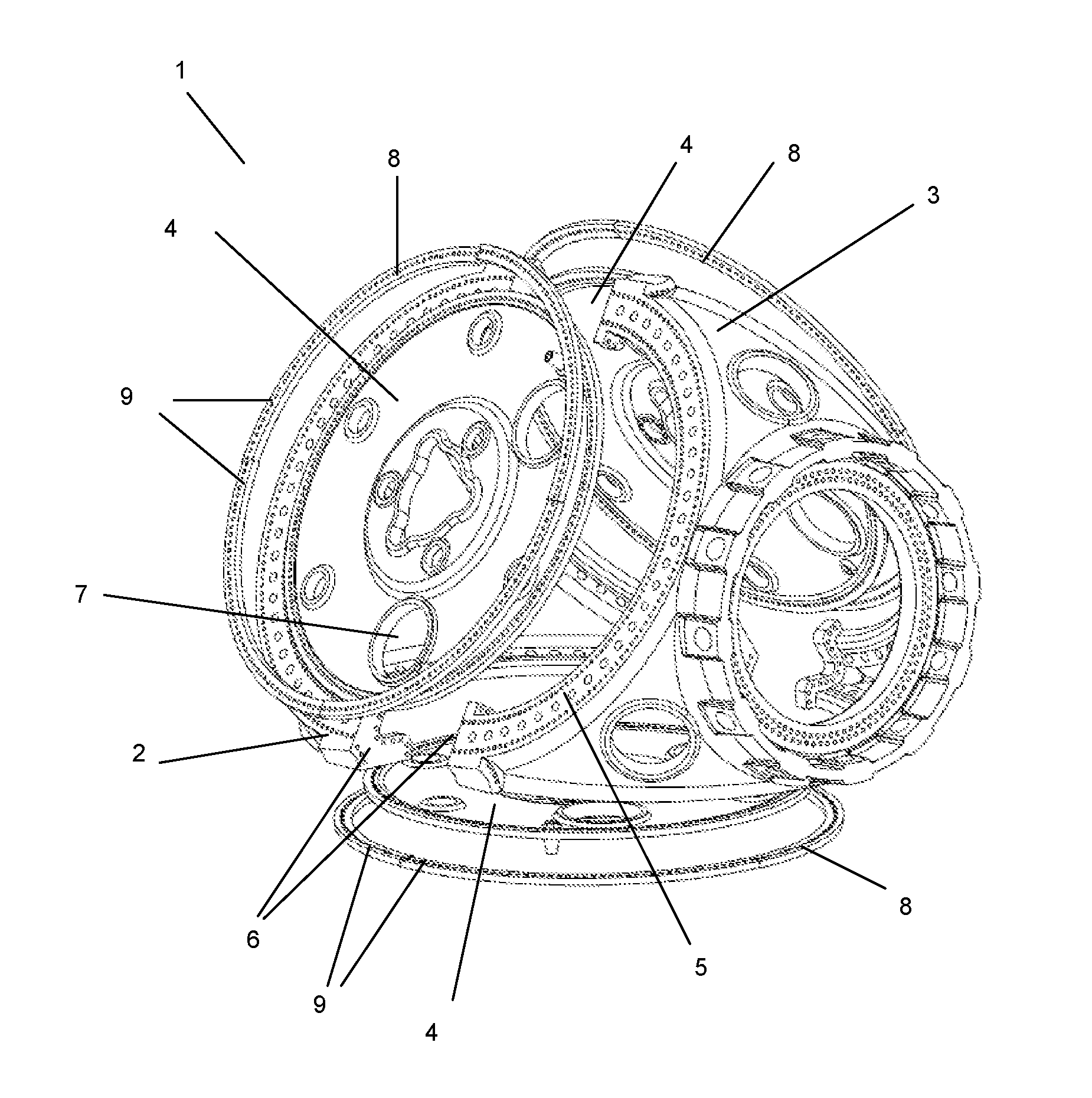
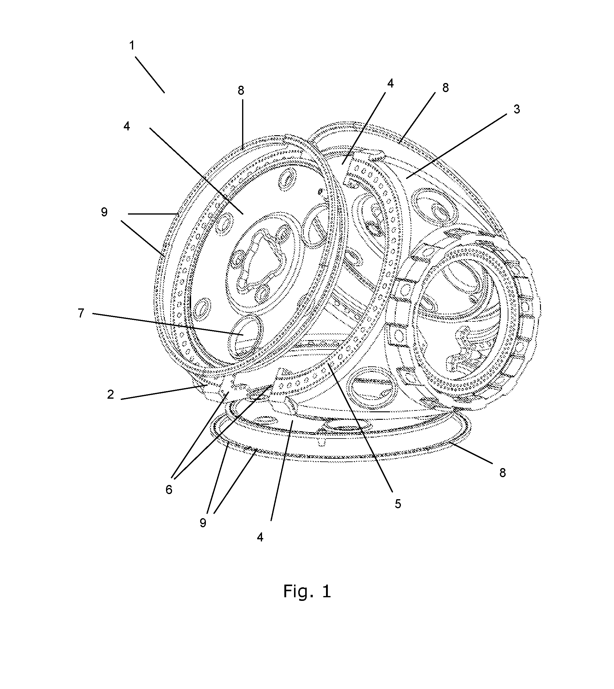
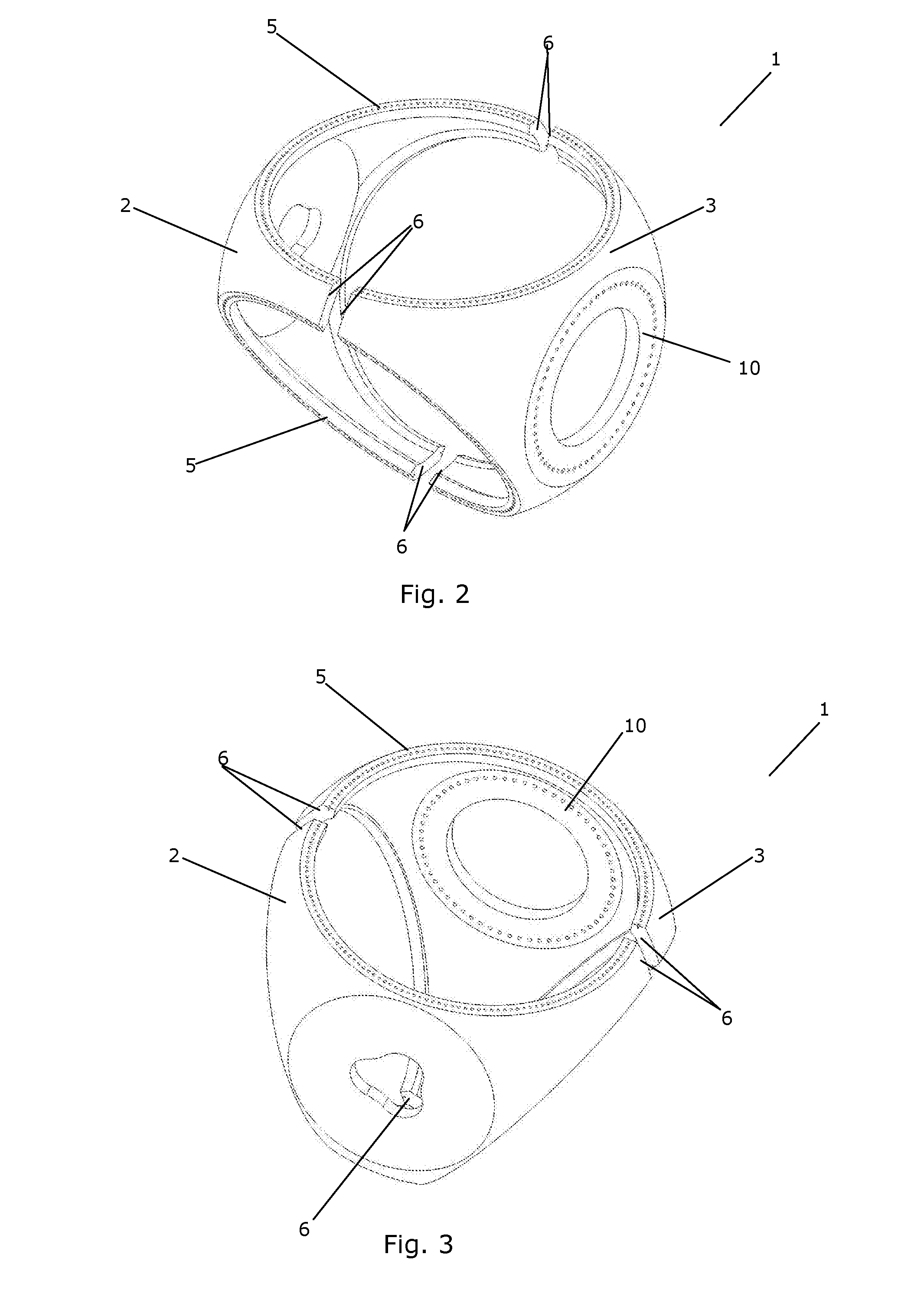
[0049]FIGS. 1-3 are exploded views of a hub according to the invention; and

[0050]FIGS. 4 and 5 are exploded views of a hub 1 according to an alternative embodiment of the invention.

DETAILED DESCRIPTION OF THE DRAWINGS

[0051]It should be understood that the detailed description and specific examples, while indicating embodiments of the invention, are given by way of illustration only, since various changes and modifications within the spirit and scope of the invention will become apparent to those skilled in the art from this detailed description.

[0052]FIG. 1 is an exploded view of a hub 1 according to the invention. The illustrated hub has a body which is split into two shell parts and therefore comprises a front shell part 2 which includes portions of three blade flanges 5. The front shell part 2 further comprises three connecting portions 6 being adapted to be connected to corresponding connecting portions 6 of the rear shell part 3.

[0053]The hub 1 further comprises a plate element...

second embodiment

[0062]FIGS. 4 and 5 are exploded views of a hub 1 according to the invention, again seen from two different angles and for simplicity viewed without the plate elements. The hub comprises three shell parts 11 arranged circumferentially with respect to a rotational axis of the hub 1 during operation. Similarly to the embodiment of FIGS. 2 and 3, the hub 1 comprises a main shaft flange 10 and three blade flanges 5.

[0063]Each of the shell parts 11 comprises four connecting portions 6, each being adapted to be connected to a connecting portion 6 of one of the other shell parts 11. The connecting portions 6 are arranged in such a manner that each of them intersects a blade flange 5, and half of them further intersect the main shaft flange 10. Thus, each blade flange 5 comprises a portion which forms part of one shell part 10 and a portion which forms part of another shell part 10.

[0064]The main shaft flange 10 comprises three portions, each forming part of one of the shell parts 11. The r...


PUM

PropertyMeasurementUnit
diameteraaaaaaaaaa
diameteraaaaaaaaaa
diameteraaaaaaaaaa

Abstract

The invention provides a hub for a wind turbine, the hub comprising a continuous shell being assembled from at least two shell parts. To improve stiffness of the hub, a plate element is attached within blade flanges of the assembled hub. Due to the combination between shell parts and a plate element, manufacturing and transportation is facilitated while strength and rigidity is ensured.

Description

INTRODUCTION[0001]The invention relates to a hub forming a hollow body with at least one blade flange for connection of the hub to a corresponding wind turbine blade. The hub of the invention is easy to handle and transport, even if the size of the hub is very large. The invention further relates to a method for manufacturing a hub.BACKGROUND OF THE INVENTION[0002]Modern wind turbines become larger and larger, and the size of the individual parts of the wind turbines, such as the hub, also increases. In a 3 MW turbine, the blades can be more than 50 meters long and the diameter of the blade root flange can be more than 3 meters. Due to the increasing forces, larger and stronger hubs are needed.[0003]The large parts are difficult to handle and transport from the manufacturing facility to the operating site of the wind turbine.[0004]Typically, the hub is cast in one piece, and the casting process becomes more expensive and the number of supplies reduces as the parts increase in size.[...

Claims


Application Information

Patent Timeline
Patent Type & Authority Applications(United States)
IPC IPC(8): F03D1/06F03D1/00
CPCF03D1/001F03D1/0691F03D1/0658F05B2230/60F03D13/10Y02E10/72Y10T29/49826Y02P70/50
Inventor BITSCH, MICHAEL LUNDGAARDNEUBAUER, JESPER LYKKEGAARD
Owner VESTAS WIND SYST AS
Why Eureka
Try Eureka