
Power source apparatus, and vehicle and power storage device equipped with that power source apparatus

a technology for power source devices and power sources, which is applied in secondary cell servicing/maintenance, battery components, battery stacks, etc., can solve the problems of limiting the region where the shield plate is disposed for protection, the upper surface of the battery stack, etc., and achieves compact power source devices. , the effect of dissipating external nois

Inactive Publication Date: 2014-08-07
SANYO ELECTRIC CO LTD
View PDF5 Cites 72 Cited by
  • Summary
  • Abstract
  • Description
  • Claims
  • Application Information

AI Technical Summary

Benefits of technology

The present invention provides a power source apparatus with a battery stack, circuit board, circuit board holder, and conducting shield plate. The shield plate can cover the circuit board to protect it from electromagnetic interference. The power source apparatus can be designed to be compact and without the need for additional shield plating. Additionally, the invention provides a power source apparatus with metal endplates and binding pieces that serve as shielding material on the under surface of the circuit board. The invention reduces the extent of area requiring shielding by the shield plate and simplifies the anti-noise strategy.

Problems solved by technology

This limits the region where the shield plate is disposed for protection from external noise to the upper surface of the battery stack.

Method used


Image

  • Power source apparatus, and vehicle and power storage device equipped with that power source apparatus
  • Power source apparatus, and vehicle and power storage device equipped with that power source apparatus
  • Power source apparatus, and vehicle and power storage device equipped with that power source apparatus

Examples


first embodiment

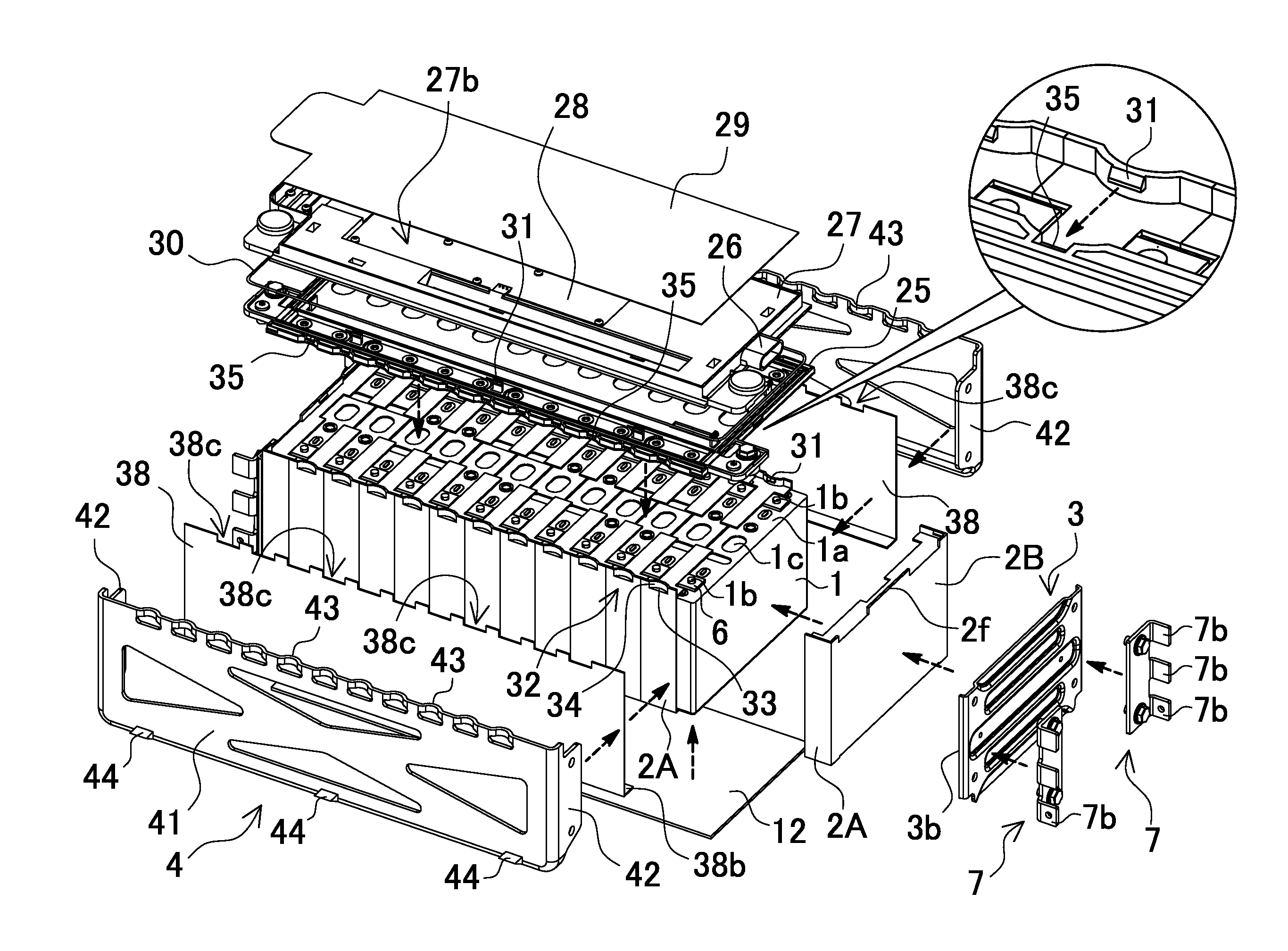
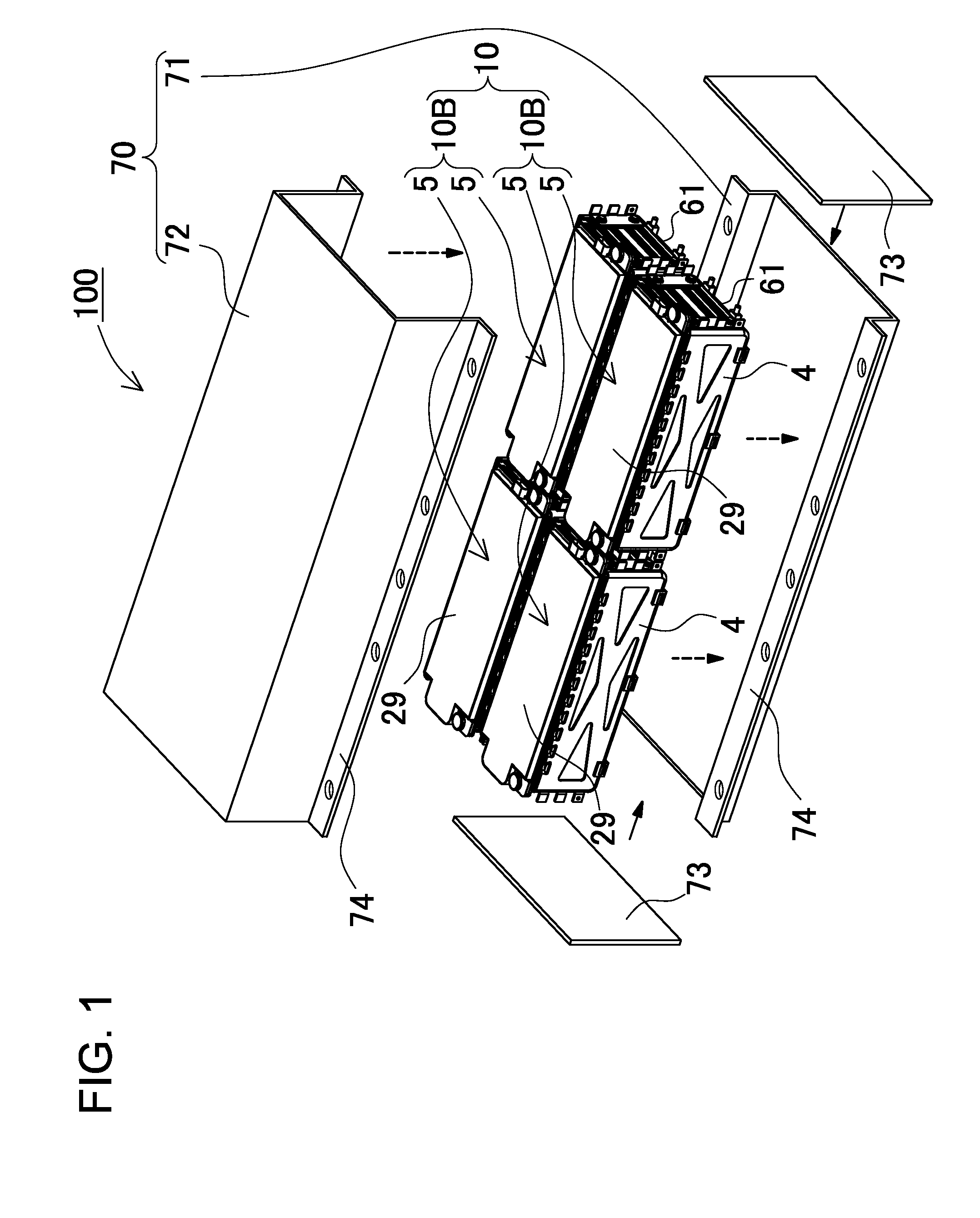
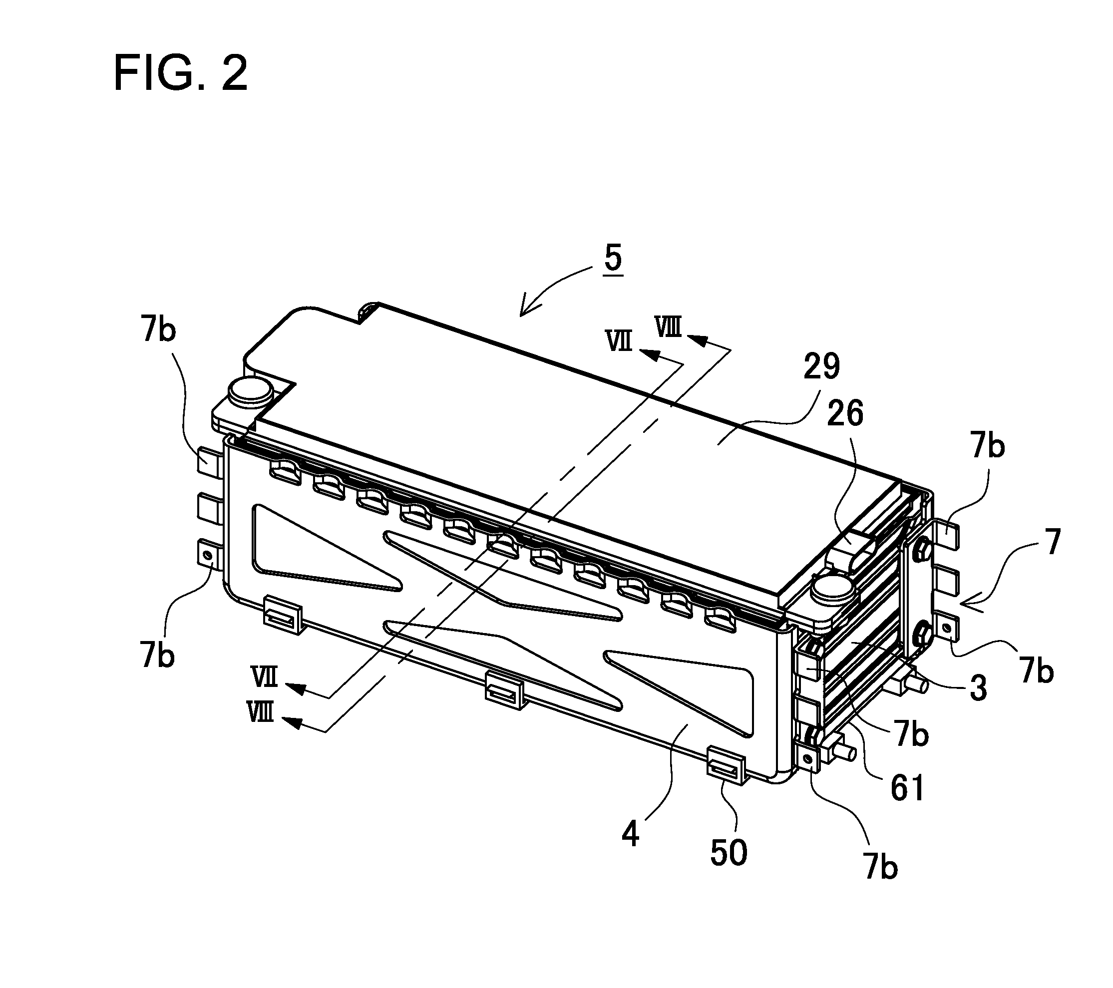
[0040]As the power source apparatus 100 for the first embodiment of the present invention, FIGS. 1-8 illustrate an example of an automotive power source apparatus suitable for installation on-board a vehicle. This power source apparatus 100 is primarily carried on-board an electric-powered vehicle such as a hybrid vehicle or electric vehicle, and is used to drive the vehicle by supplying power to the driving motor. However, the power source apparatus of the present invention can also be used in electric-powered vehicles other than hybrid or electric vehicles, and can also be used in applications that require high power output other than electric-powered vehicles.

(Power Source Apparatus 100)

[0041]As shown in the exploded perspective view of FIG. 1, the power source apparatus 100 has a box-shaped external appearance with a rectangular upper surface. The power source apparatus 100 has a battery assembly 10 (or a plurality of battery assemblies 10) held inside a box-shaped outer case 70...


PUM

PropertyMeasurementUnit
thermally conductingaaaaaaaaaa
voltageaaaaaaaaaa
output voltageaaaaaaaaaa

Abstract

A power source apparatus provided with a battery stack having a plurality of rectangular shaped rechargeable battery cells stacked together, a circuit board carrying electronic circuitry electrically connected with the rechargeable battery cells, a circuit board holder disposed on the upper surface of the battery stack that establishes circuit board storage space to hold the circuit board, and a conducting shield plate installed on top of the circuit board holder that closes-off at least the upper surface of the circuit board storage space holding the circuit board inside.

Description

BACKGROUND OF THE INVENTION[0001]1. Field of the Invention[0002]The present invention relates to a power source apparatus primarily used to power a motor that drives a vehicle such as a hybrid vehicle (hybrid car, hybrid electric vehicle, HEV) or electric vehicle (EV, electric automobile) or used as a high current power source apparatus for applications such as power storage in the home or in industry, and to a vehicle and power storage device equipped with that power source apparatus.[0003]2. Description of the Related Art[0004]There is demand for power source apparatus with high output, such as those for automotive applications. These types of power source apparatus have many battery cells connected in series to increase the output voltage and deliver high power. To drive a high output motor, circuitry connected to the motor must be high voltage circuitry. The high voltage circuitry is switched ON and OFF via high voltage relays (contactors).[0005]A plurality of individual battery...

Claims


Application Information

Patent Timeline
Patent Type & Authority Applications(United States)
IPC IPC(8): H01M2/10H01M10/625H01M10/6554B60L11/18H01M10/42B60L50/64
CPCH01M2/1077B60L11/1877H01M10/4257H01M2220/20H01M10/5016H01M2/1083H01M2/1094H01M10/5053H01M10/625H01M10/647H01M10/6556H01M10/6554H01M10/613B60L50/66Y02T10/70Y02E60/10H01M50/249H01M50/224H01M50/209B60L50/64H01M50/284H01M50/276H01M50/264H01M50/24
Inventor FUJII, KAZUHIROSETO, TAKASHI
Owner SANYO ELECTRIC CO LTD
Learn More