Automatic analyzer

Active Publication Date: 2014-08-07
HITACHI HIGH-TECH CORP
View PDF4 Cites 18 Cited by
  • Summary
  • Abstract
  • Description
  • Claims
  • Application Information

AI Technical Summary

Benefits of technology

[0014]It can be realized that an automatic analyzer and a method for judging normal and abnormal of the dispensing operation detect abnormal conditio

Problems solved by technology

At the dispensing operation using a dispensing probe, a predetermined quantity of liquid may not be dispensed correctly because of a liquid surface detection failure caused by bubbl

Method used


Image

  • Automatic analyzer
  • Automatic analyzer
  • Automatic analyzer

Examples


embodiments

The Embodiment 1

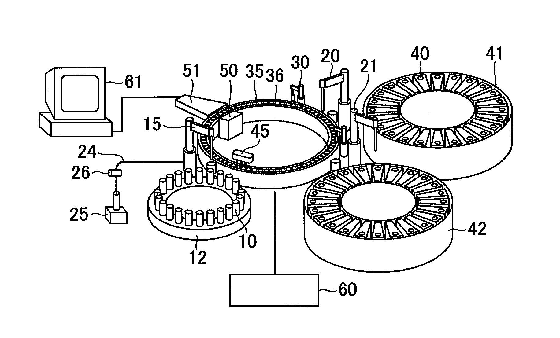
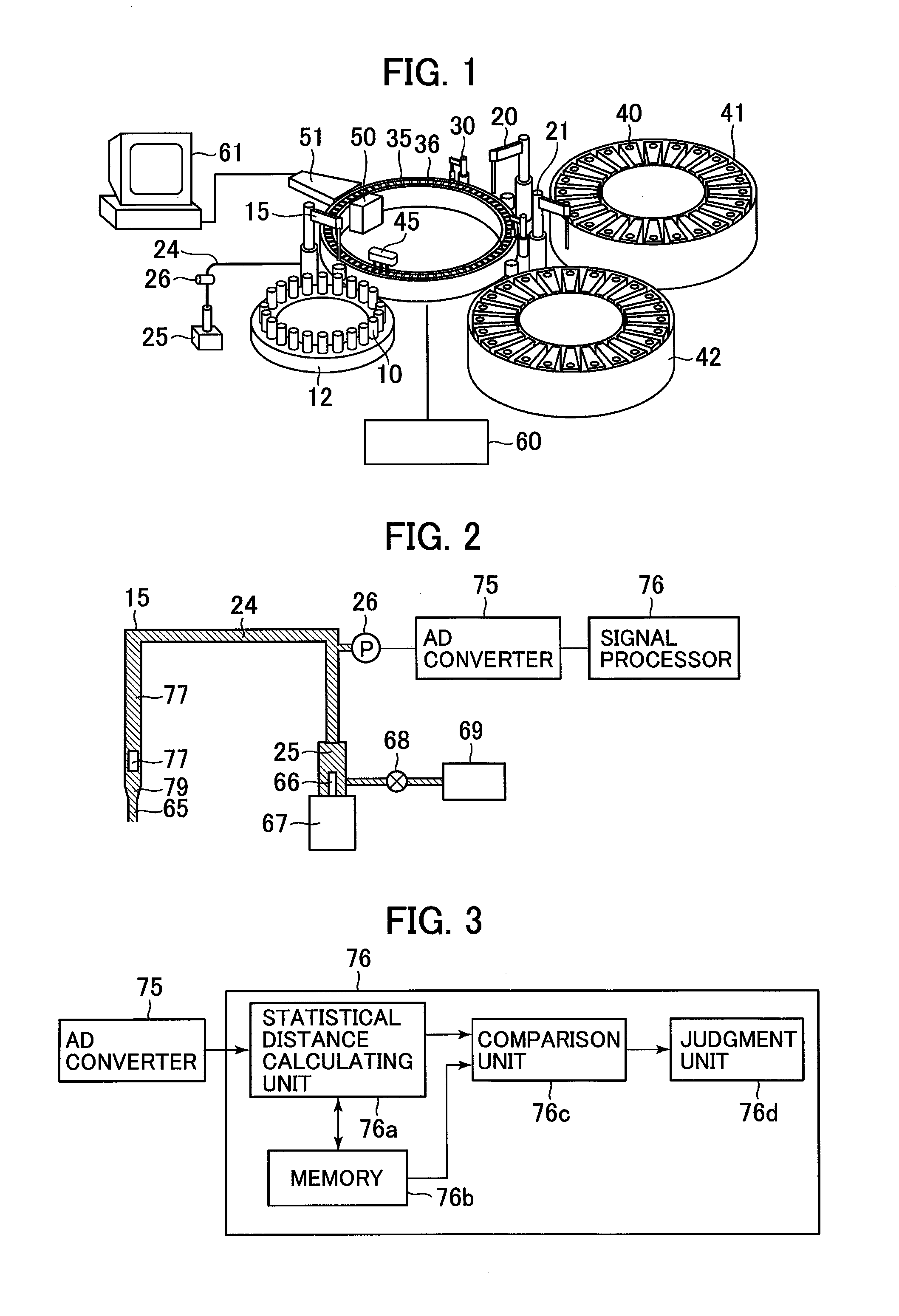
[0029]FIG. 1 is a schematic construction drawing of an automatic analyzer to which the present invention is applied, FIG. 2 being a drawing for explaining the main part (probe pressure signal processing unit) in the first embodiment of the present invention.

[0030]In FIG. 1, the automatic analyzer includes a sample disk 12 capable for loading a plurality of sample containers 10 for holding samples, the first reagent disk 41 and the second reagent disk 42 capable for loading a plurality of reagent containers 40 for holding reagents, and a reaction disk 36 on which a plurality of reaction containers 35 are arranged at its circumference.

[0031]Further, the automatic analyzer includes a sample probe 15 for dispensing a sample sucked from the sample container 10 into the reaction container 35, the first reagent probe 20 for dispensing the reagent sucked from the reagent container 40 in the first reagent disk 41 into the reaction container 35, the second reagent probe 21 dis...

embodiment 2

The Embodiment 2

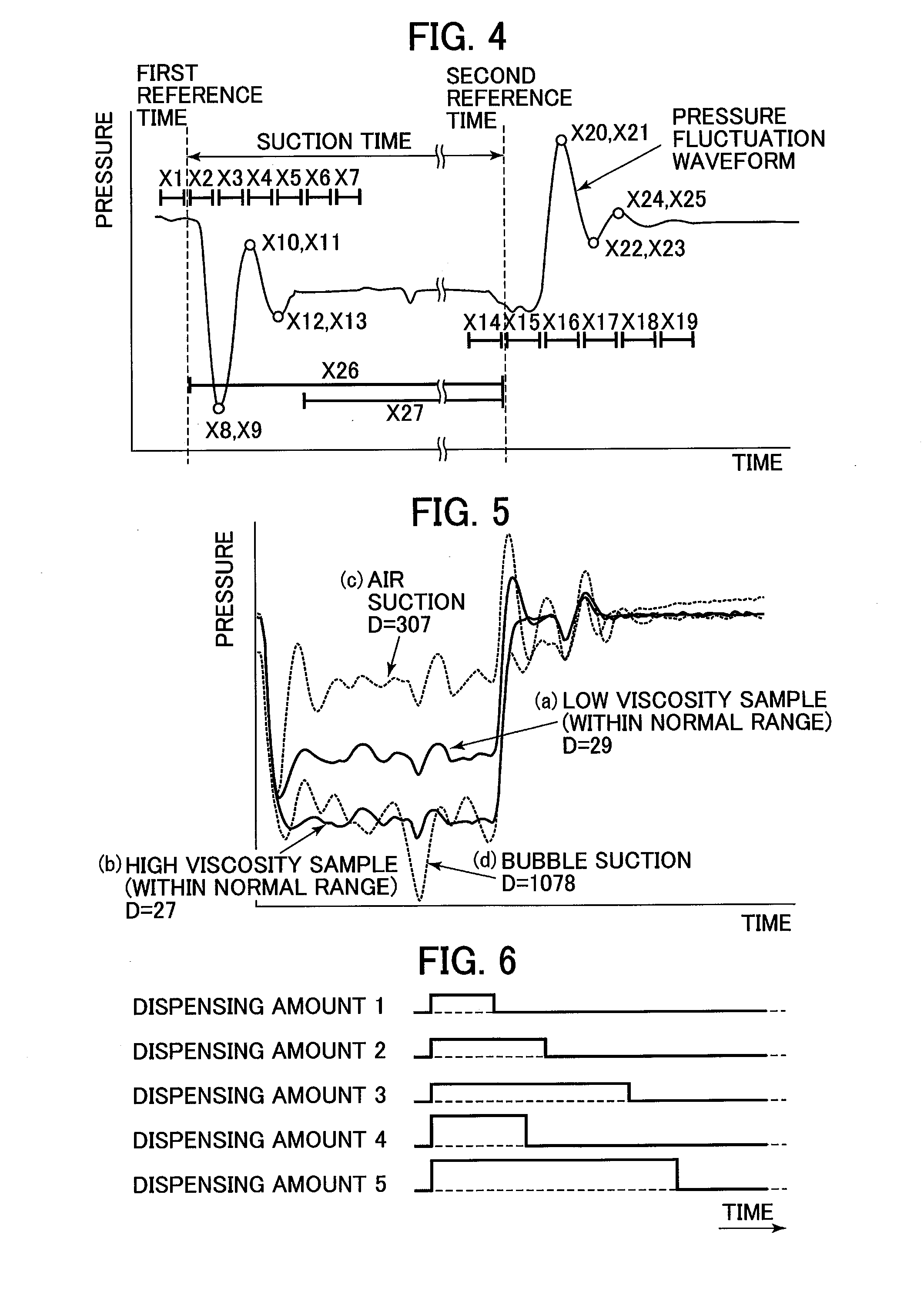
[0083]FIG. 12 is the flowchart of the discrimination operation of the embodiment 2 which is other embodiment of the present invention. The different point from the embodiment 1 is that the feature variables of both waveforms of the suction and discharge operations without separating the suction operation from the discharge operation after the discharging operation, and the threshold value th is compared with the calculated Statistical distance D from the normal group data. Other constructions are same as the embodiment 1, so that the detailed description and drawings are omitted. Further, the steps as same as the steps shown in FIG. 11 are designated by the same reference numerals in FIG. 12.

[0084]In FIG. 12, after the suction operation (the step S1) and the discharge operation (the step S6) are executed, the feature variables of the suction waveform and the discharge waveform being extracted (the steps S2 and step S7), the Statistical distance D from the normal grou...

embodiment 3

The Embodiment 3

[0091]FIG. 13 is the flowchart of the discrimination operation of the embodiment 3 which is other embodiment of the present invention. The steps S1, S6, (S2, S7), (S3, S8), and (S4, S9) of the embodiment 3 are equal to the steps S1, S6, (S2, S7), (S3, S8), and (S4, S9) of the embodiment 2. The difference between the embodiment 3 and the embodiment 2 is that the cases of the occurrences of the air suction and the clogging are judged in the embodiment 3.

[0092]In the embodiment 3, the apparatus prepares not only normal group data but also the air suction occurrence group data and the clogging occurrence group data previously. Namely, the data are stored in the memory 76b.

[0093]The Statistical distance D between the feature variables extracted from the suction and discharge operations between the normal group data is calculated firstly (the steps S3 and S8). When it is judged that the calculated distance is more than or equal to the threshold value th (the steps S4 and ...


PUM


Abstract

A plunger 66 is moved downwardly in predetermined distance while the tip of the sample probe 15 is immersed in a sample to suck the sample into the probe. A pressure sensor 26 detects the pressure fluctuation during the suction operation, an AD converter converting the signals into digital signals to send the signals for a signal processing unit 76. The signal processing unit 76 extracts feature variables data of a suction waveform to calculate the Statistical distance D from normal group data. The Statistical distance D an a threshold value th are compared with each other, it is judged that there is an abnormality in the suction operation when the Statistical distance D is more than or equal to the threshold value th. When the Statistical distance D is smaller than the threshold value th, an operation is proceeded to a discharge operation.

Description

TECHNICAL FIELD[0001]The present invention relates to an automatic analyzer analyzing components of blood or the like automatically.BACKGROUND ART[0002]An automatic analyzer dispenses samples composed of biological samples, such as blood, urine or the like into reaction containers on a reaction line from sample containers, further dispensing reagents into the reaction containers on the reaction line from reagent containers, measuring mixed solutions of samples and reagents by using a measurement device such as a photometer to execute qualification analysis or quantitative analysis.[0003]A tip of a dispensing probe is immersed into solution to be dispensed at the dispensing operations of sample and reagent, the quantities of the solution attached to the outer wall of the probe becomes large in proportion to the immersion depth of the probe into the solution, so that the quantities of contamination to the probe becomes large.[0004]Accordingly, in order to reduce the immersion depth of...

Claims


Application Information

Patent Timeline
IPC IPC(8): G01N35/10
CPCG01N35/1002G01N2035/1062G01N35/1011G01N35/1016G01N2035/1018Y10T436/119163
Inventor YAMAZAKI, ISAONISHIDA, MASAHARUKAMIHARA, KUMIKOTAMEZANE, HIDETO
Owner HITACHI HIGH-TECH CORP
Why Eureka
Try Eureka