Roller bearing

a roller bearing and roller technology, applied in the field of roller bearings, can solve the problems of large amount of wear debris, increased surface roughness, and increased wear debris, and achieve the effect of improving cooling effect and prolonging service li

Active Publication Date: 2014-08-07
NTN CORP
View PDF7 Cites 5 Cited by
  • Summary
  • Abstract
  • Description
  • Claims
  • Application Information

AI Technical Summary

Benefits of technology

[0025]According to the roller bearing of the present invention, in the state where the rollers and the holder are incorporated between the outer ring raceway diameter and the inner ring raceway diameter, the non-contact state is kept between: the outer circumferential surfaces of the rollers; and the inner protrusions and the outer protrusions provided to the pillar parts. Hence, lubricant oil on the outer surfaces of the rollers is not scraped by the inner protrusions and the outer protrusions, and wear debris is not caught therebetween. Moreover, dusts such as metal wear debris mixed in the lubricant oil are not accumulated in portions of the inner protrusions and the outer protrusions, and the lubricant oil smoothly flows in the gaps between the rollers and the pockets.
[0026]Accordingly, in the roller bearing of the present invention, surface indentation and oil film shortage are less likely to occur in the rollers. Hence, even if the roller bearing is used for a planetary gear reducer in which metal wear debris is likely to occur, the service life thereof is longer.
[0027]Moreover, the gap interval of the inner oil passage formed between the inner ring raceway and the inner diameter of the holder is set to be larger than the gap interval of the outer oil passage formed between the outer ring raceway and the outer diameter of the holder. Hence, a larger amount of lubricant oil is circulated from the inner oil passage to the outer oil passage, and a cooling effect is improved.

Problems solved by technology

As a result, there occurs a problem that the roller 26 in each pocket 28 rubs against the dusts, particularly metal wear debris such as iron powder accumulated in portions of the inner protrusions 31 and the outer protrusions 32, and thus is worn away in a short time.
Particularly in recent years, for example, gear reducer manufacturers tend to omit finish processing of gears along with demands for cost reduction, so that the surface roughness is increasing.
As a result, rough protrusions come off due to mesh between the gears, and a large amount of wear debris is generated in many cases.
Accordingly, preventing rollers from being worn by metal wear debris is becoming an important issue.

Method used


Image

  • Roller bearing
  • Roller bearing
  • Roller bearing

Examples


Embodiment Construction

[0035]An embodiment of the present invention is described with reference to FIG. 1 to FIG. 4.

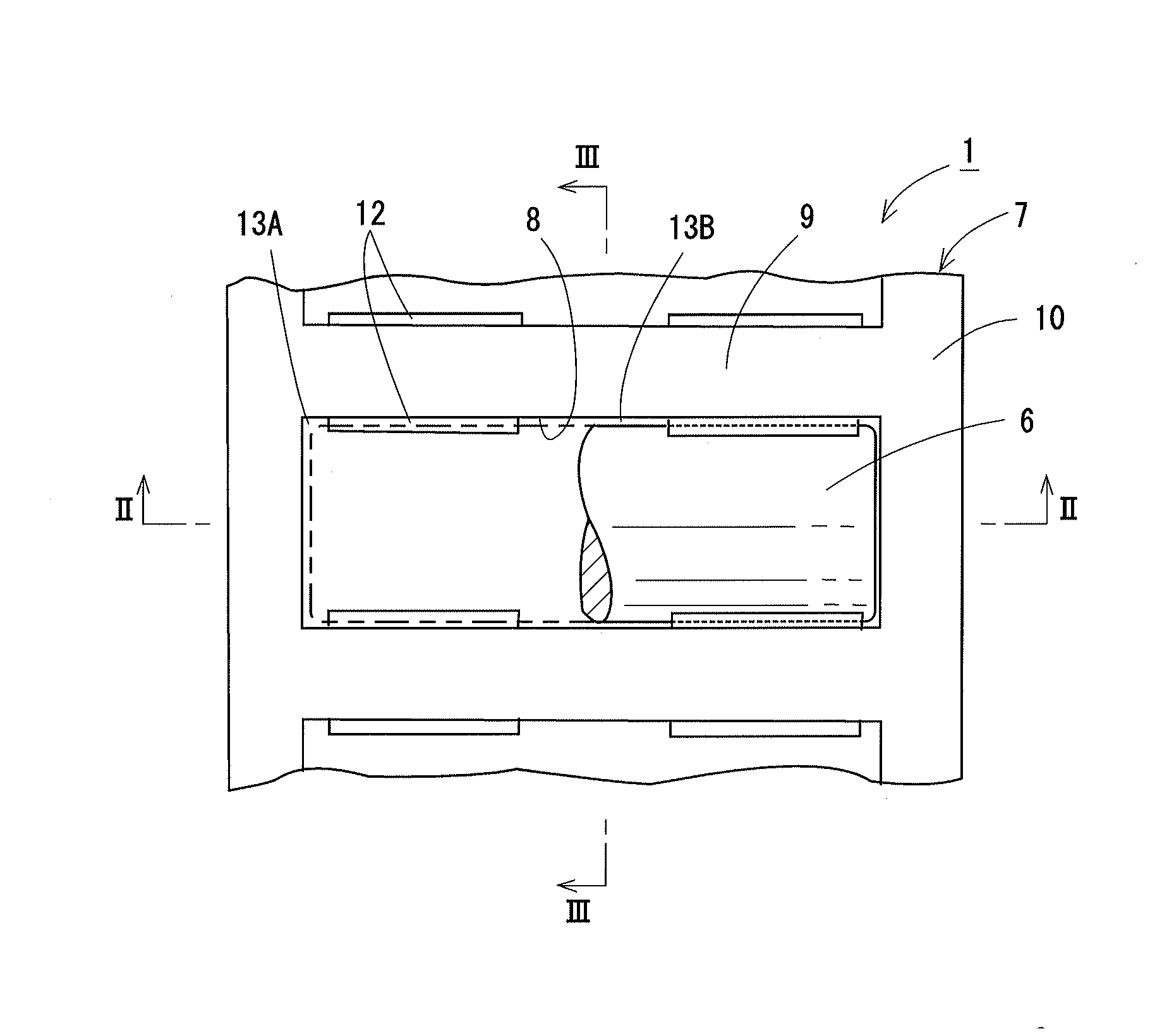
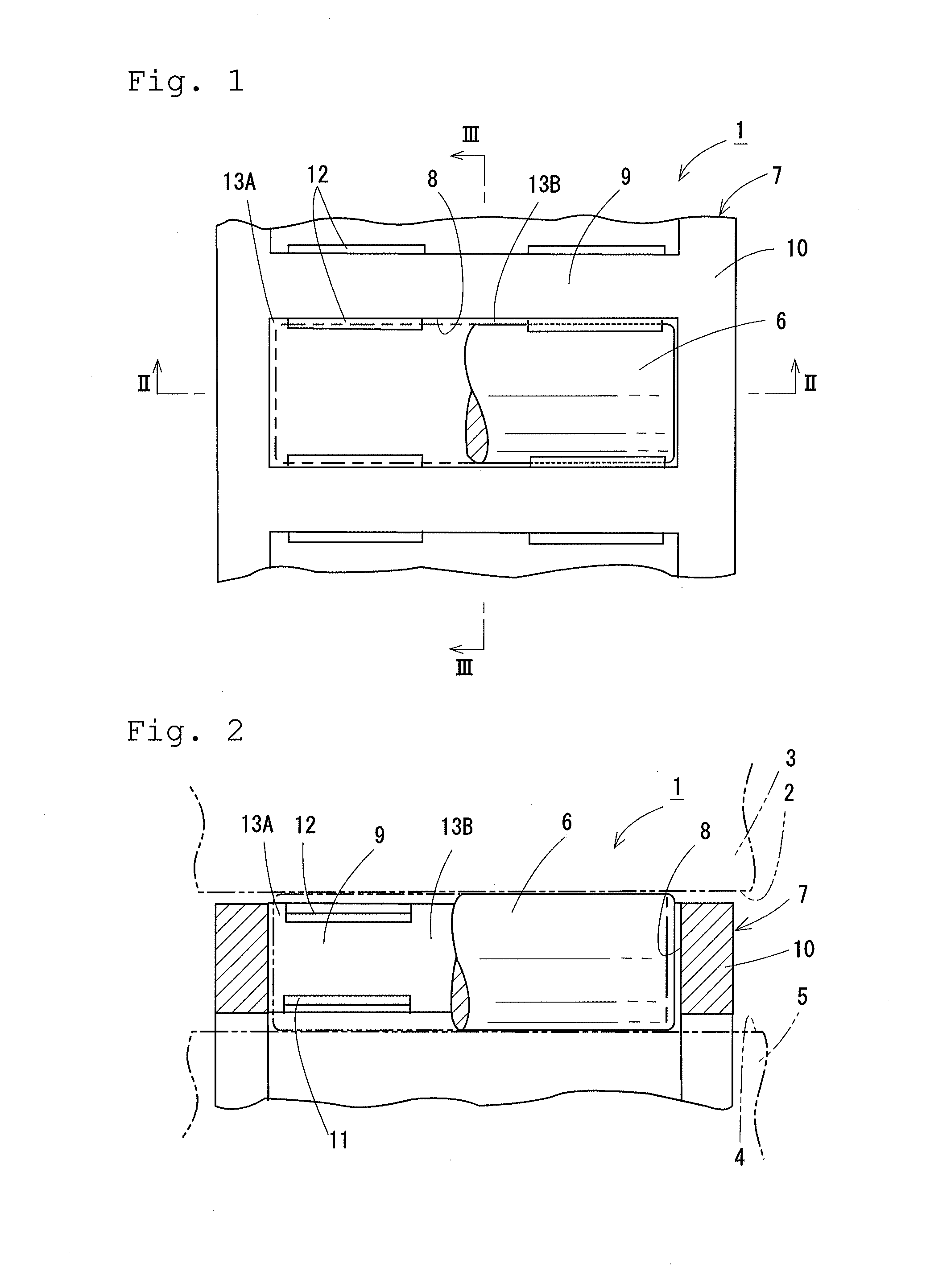
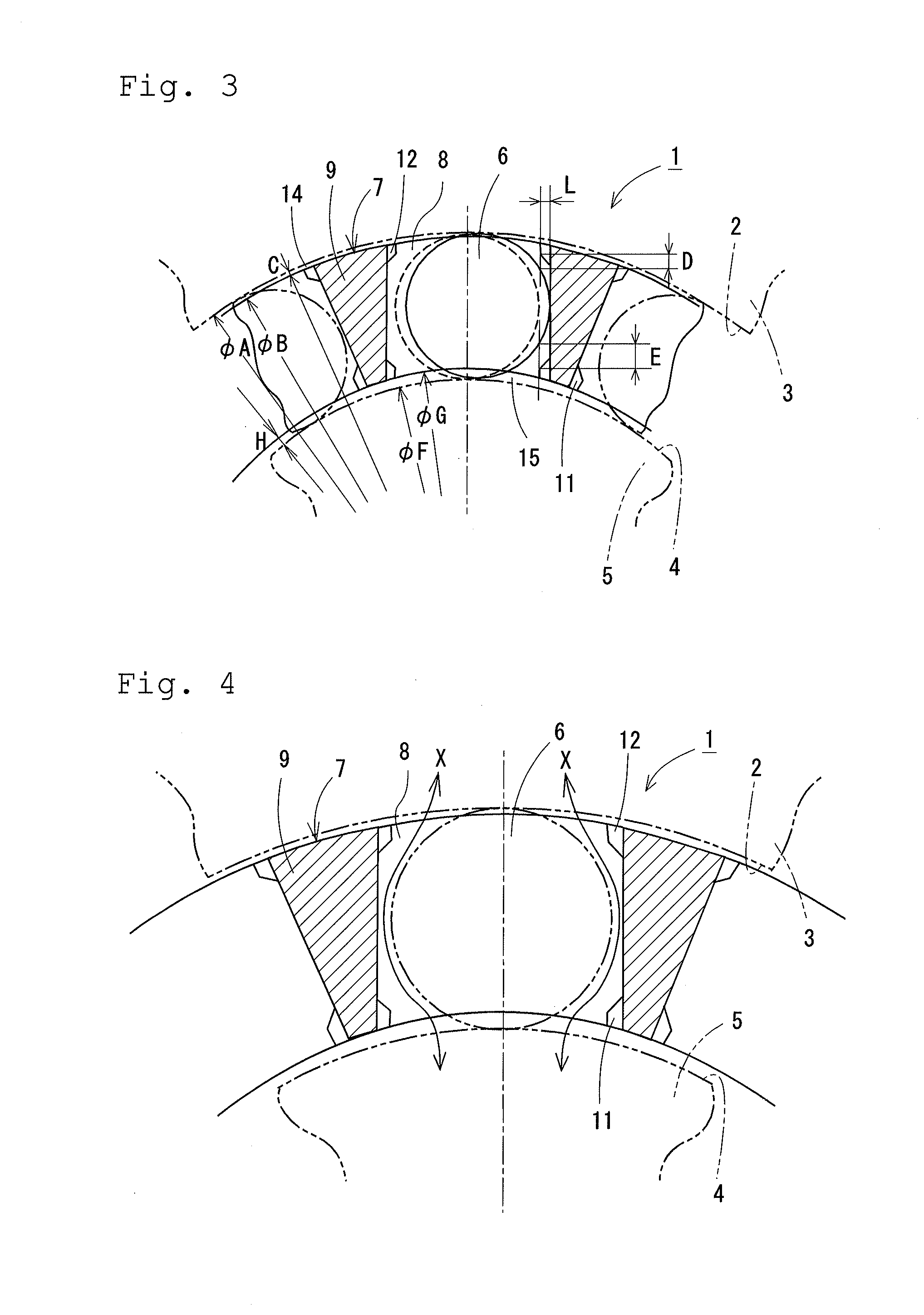
[0036]A roller bearing 1 includes: an outer member 3 having a cylindrical outer ring raceway 2 on its inner circumferential surface; an inner member 5 having a cylindrical inner ring raceway 4 on its outer circumferential surface; and a plurality of rollers 6 that are rollably provided between the outer ring raceway 2 and the inner ring raceway 4.

[0037]The rollers 6 are each formed in a cylindrical shape using a metal material or the like, are configured as needle rollers, bar rollers, or the like, and are regularly arranged in and held by a holder 7 the entirety of which is formed in a cylindrical shape.

[0038]The holder 7 has rectangular pockets 8 that respectively regularly house the rollers 6, at predetermined intervals in its circumferential direction, and is formed by injection molding or the like using a resin material. The pockets 8 are formed so as to penetrate through the holder 7 f...


PUM


Abstract

Surface indentation and oil film shortage on rollers is prevented and longer service life of a roller bearing is achieved, by preventing wear debris from being caught and accumulated in pockets of a holder of the roller bearing. Positions and dimensional relations of the diameters of inner and outer ring raceways, the inner and outer diameters of the holder, and inner and outer protrusions which are provided to pillar parts of the holder to prevent the rollers from coming off are defined such that the inner and outer protrusions of the pillar parts always do not come into contact with the outer circumferential surfaces of the rollers in the state where the rollers and the holder are incorporated between inner and outer members. As a result, lubricant oil is smoothly circulated in gaps formed between the outer circumferential surfaces of the rollers and the pillar parts of the holder.

Description

TECHNICAL FIELD[0001]The present invention relates to a roller bearing suitably used for a planetary gear reducer.BACKGROUND ART[0002]As illustrated in FIG. 5 to FIG. 7, a roller bearing 21 includes: an outer member 23 having a cylindrical outer ring raceway 22 on its inner circumferential surface; an inner member 25 having a cylindrical inner ring raceway 24 on its outer circumferential surface; and a plurality of rollers 26 that are rollably provided between the outer ring raceway 22 and the inner ring raceway 24.[0003]The rollers 26 are rollably held by a holder 27 the entirety of which is formed in a cylindrical shape. The holder 27 has pockets 28 that respectively house the rollers 26, at predetermined intervals in its circumferential direction. The holder 27 includes: pillar parts 29 between the pockets 28 adjacent to each other in the circumferential direction; and annular parts 30 on both sides in the axial direction of the pillar parts 29.[0004]Inner protrusions 31 and oute...

Claims


Application Information

Patent Timeline
Patent Type & Authority Applications(United States)
IPC IPC(8): F16C33/46F16C33/66F16H1/28F16C33/56
CPCF16C33/4605F16H1/28F16C33/6681F16C33/56F16C19/26F16C2240/46F16C33/4617F16C33/4629F16C33/4635F16C33/4676F16H2057/085F16C2361/61F16C33/4623
Inventor NAKAGAWA, TSUTOMUNISHIMURA, MASASHIOISHI, SHINJI
Owner NTN CORP
Why Eureka
Try Eureka