Multi-Axis Tilt Sensor for Correcting Gravitational Effects on the Measurement of Pressure by a Capacitance Diaphragm Gauge

a capacitance diaphragm and tilt sensor technology, applied in the field of capacitance diaphragm gauges, can solve the problems of negative influence on the accuracy of the measurement of pressure by a cdg, offset in the pressure reading, and inability to meet the needs of measurement,

Active Publication Date: 2014-08-07
SUMITOMO SHI CRYOGENICS OF AMERICA
View PDF2 Cites 6 Cited by
  • Summary
  • Abstract
  • Description
  • Claims
  • Application Information

AI Technical Summary

Benefits of technology

[0012]A system and method disclosed herein compensate for effects of gravity on the diaphragm of the CDG that may cause inaccurate pressure measurements. The CDG generates a measured absolute pressure value in response to an applied absolute pressure on an input of the CDG. A pressure measuring circuit generates a measured value of an applied absolute pressure provided to an input of the CDG. A tilt sensor generates at least one tilt sensor output value that is responsive to an orientation of the CDG with respect to the earth's surface. A processing system adjusts the measured absolute pressure value by a calibration factor to generate a calibrated absolute pressure value representing the applied absolute pressure, wherein the calibration factor is selected in response to the at least one tilt sensor output value.
[0013]An aspect in accordance with embodiments disclosed herein is a method for compensating for effects of gravity on the diaphragm of a capacitance diaphragm gauge (CDG) that measures an absolute pressure applied to an input of the CDG, wherein the CDG is positionable with the diaphragm in differing orientations with respect to the earth's surface. The method comprises applying an applied absolute pressure to the input of the CDG, and generating a measured pressure value responsive to the applied absolute pressure. The method further comprises determining an orientation of the CDG with respect to the earth's surface using a tilt sensor coupled to the CDG, and adjusting the measured pressure value by a calibration factor determined by the orientation of the CDG to generate a calibrated pressure value that corresponds to the applied absolute pressure. In certain embodiments of the method, the measured pressure value is a first digital value, the calibration factor is a second digital value, and the calibrated pressure value is a third digital value. In certain embodiments of the method, the calibration factor is determined by applying a known absolute pressure to the input of the CDG, and varying the orientation of the CDG with respect to the earth's surface to a plurality of different orientations while monitoring the measured pressure value at each of a plurality of different orientations. A difference between the measured absolute pressure and the known absolute pressure is determined at each of the plurality of different orientations. A respective calibration factor for each of the plurality of different orientations is generated based on the difference between the measured absolute pressure and the known absolute pressure at each respective orientation. In certain embodiments of the method, each respective calibration factor is stored in a lookup table indexed by the plurality of different orientations. In certain embodiments of the method, the calibration factors at each of the plurality of different orientations are used to produce a calibration equation that generates a calibration factor in response to a determined orientation of the CDG.
[0014]Another aspect in accordance with embodiments disclosed herein is a system that compensates for effects of gravity on the diaphragm of a capacitance diaphragm gauge (CDG) that generates a measured absolute pressure value in response to an applied absolute pressure on an input of the CDG, wherein the CDG is subjected to a variable orientation of the CDG with respect to the earth's surface. The system comprises a pressure measuring circuit that generates a measured value of an applied absolute pressure provided to an input of the CDG. The system further comprises a tilt sensor that generates at least one tilt sensor output value that is responsive to an orientation of the CDG with respect to the earth's surface. The system further comprises a processing system that adjusts the measured absolute pressure value by a calibration factor to generate a calibrated absolute pressure value representing the applied absolute pressure. The calibration factor is selected in response to the at least one tilt sensor output value. In certain embodiments of the system, the measured absolute pressure value is a first digital value, the calibration factor is a second digital value, and the calibrated absolute pressure value is a third digital value. In certain embodiments of the system, the CDG generates an analog signal that represents the measured value of the absolute pressure, and the system further includes an analog-to-digital converter that converts the analog signal to the first digital value. In certain embodiments of the system, the processing system obtains the calibration factor from a lookup table indexed by the at least one tilt sensor output value. In certain embodiments of the system, the processing system calculates the calibration factor using a calibration equation wherein the at least one tilt sensor output value is an input variable to the calibration equation.

Problems solved by technology

The accuracy of the measurement of pressure by a CDG can be negatively impacted by several factors, one of which is a change in the orientation of the CDG with respect to a conventional orientation in which an X-Y plane of the CDG is parallel to the surface of the earth and the Z axis of the CDG is normal to the surface of the earth.
This biased deflection can result in an offset in the pressure reading.
However, this is not a satisfactory solution for many users who want to be able to replace an existing CDG with a new CDG without having to recalibrate each time a CDG is replaced.

Method used


Image

  • Multi-Axis Tilt Sensor for Correcting Gravitational Effects on the Measurement of Pressure by a Capacitance Diaphragm Gauge
  • Multi-Axis Tilt Sensor for Correcting Gravitational Effects on the Measurement of Pressure by a Capacitance Diaphragm Gauge
  • Multi-Axis Tilt Sensor for Correcting Gravitational Effects on the Measurement of Pressure by a Capacitance Diaphragm Gauge

Examples


Embodiment Construction

[0025]The improvements to capacitance diaphragms are disclosed herein with respect to exemplary embodiments of a system and a method. The embodiments are disclosed for illustration of the system and the method and are not limiting except as defined in the appended claims. Although the following description is directed to a particular embodiment of a capacitance diaphragm gauge, it should be understood that the disclosed system and method can be applied to other embodiments of capacitance diaphragm gauges.

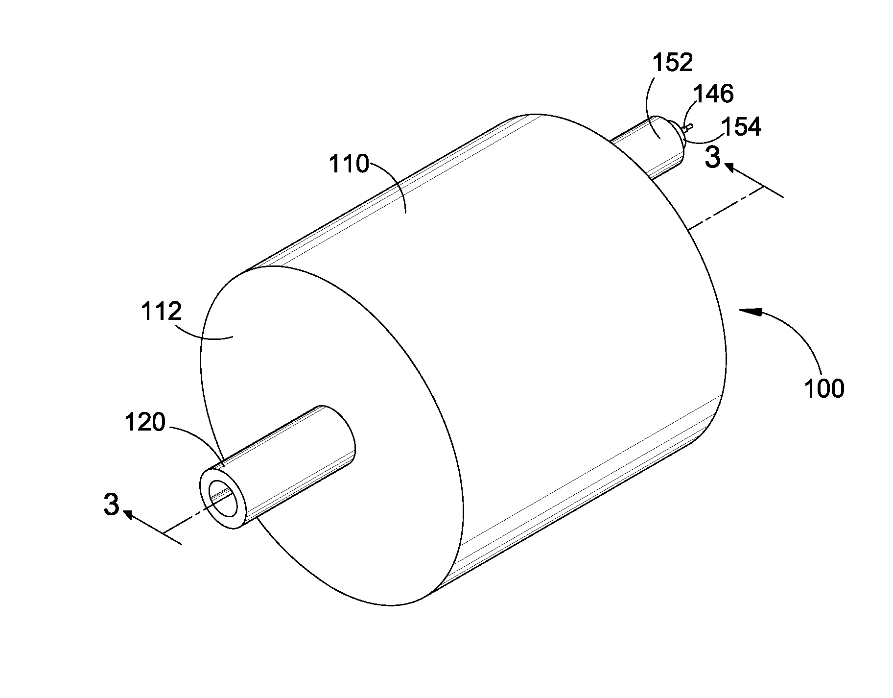
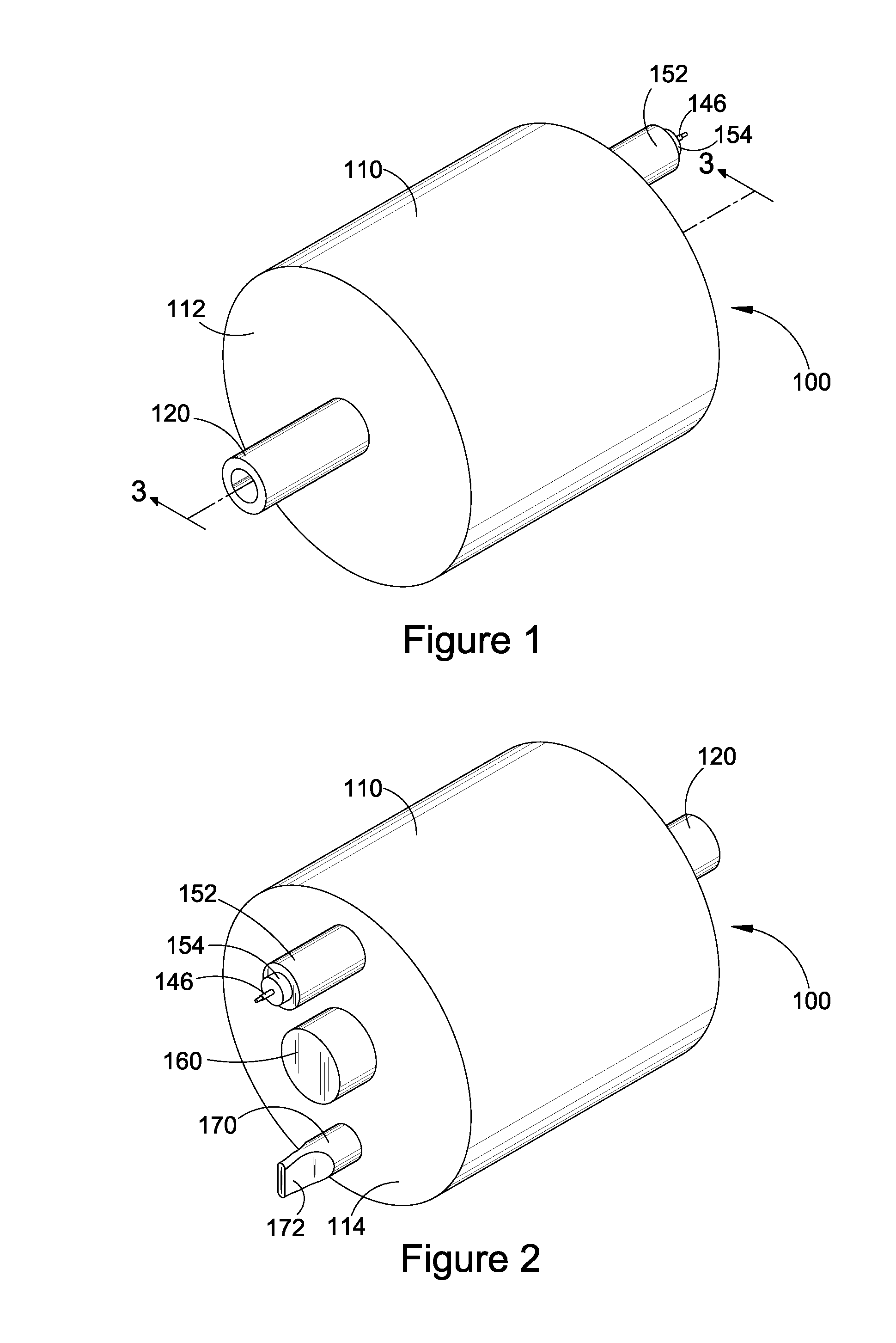
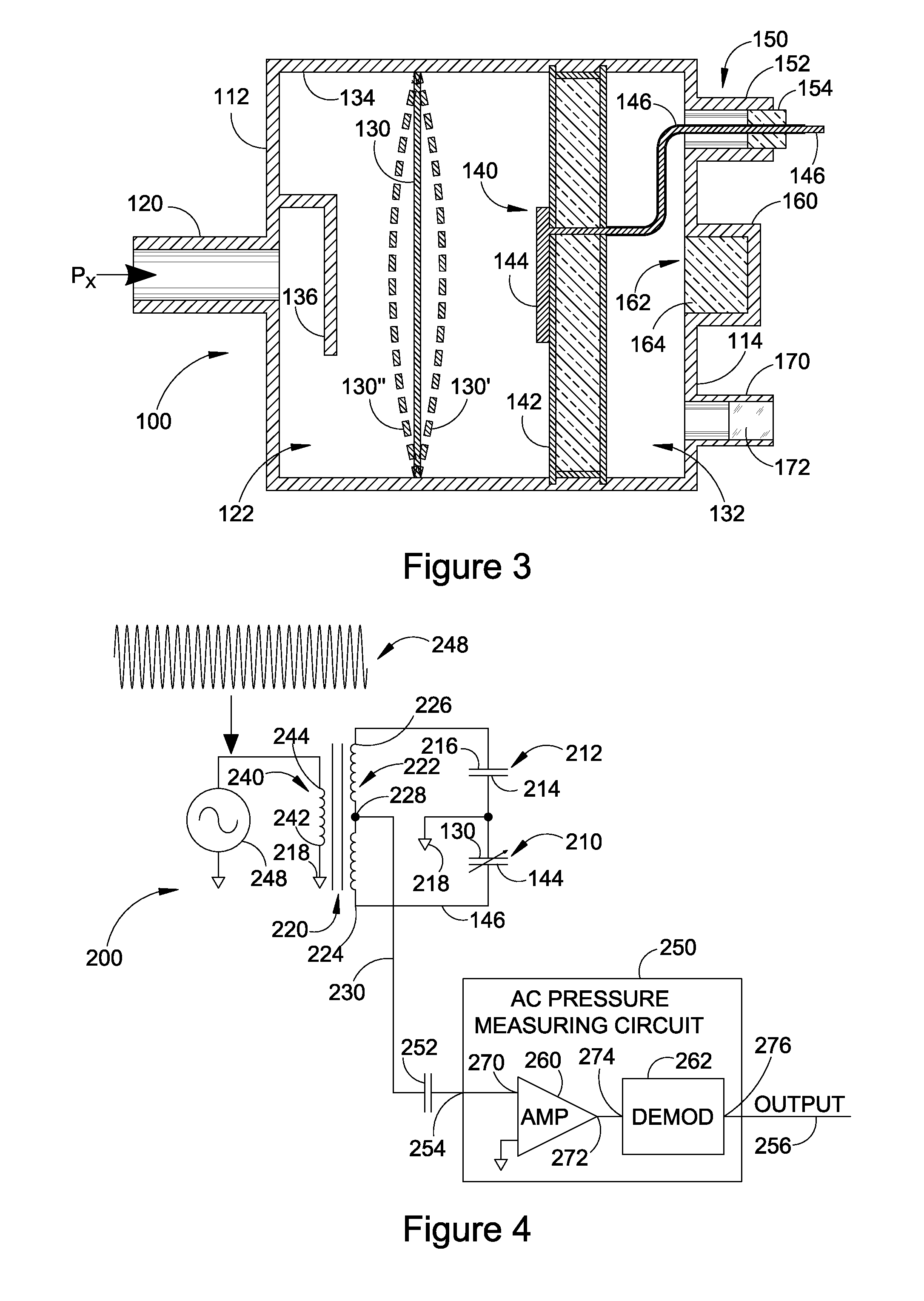
[0026]FIG. 1 illustrates a front perspective view of an exemplary capacitance diaphragm gauge (CDG) 100, which is installable into a pneumatic system (not shown) to measure the pressure within the system. In particular, the CDG is used to measure very low pressures resulting from evacuation of the pneumatic system. FIG. 2 illustrates a rear perspective view of the CDG of FIG. 1 which is rotated 180° from the view in FIG. 1. FIG. 3 illustrates a cross-sectional view of the CDG taken ...


PUM

PropertyMeasurementUnit
pressureaaaaaaaaaa
thicknessaaaaaaaaaa
thicknessaaaaaaaaaa

Abstract

A system and method compensate for effects of gravity on the diaphragm of a capacitance diaphragm gauge (CDG). The CDG generates a measured absolute pressure value in response to an applied absolute pressure on an input of the CDG. The CDG is subjected to a variable orientation of the CDG with respect to the earth's surface that can cause inaccurate pressure measurements. A pressure measuring circuit generates a measured value of an applied absolute pressure provided to an input of the CDG. A tilt sensor generates at least one tilt sensor output value that is responsive to an orientation of the CDG with respect to the earth's surface. A processing system adjusts the measured absolute pressure value by a calibration factor to generate a calibrated absolute pressure value representing the applied absolute pressure, wherein the calibration factor is selected in response to the at least one tilt sensor output value.

Description

RELATED APPLICATIONS[0001]The present application claims the benefit of priority under 35 USC §119(e) to U.S. Provisional Application No. 61 / 761,226 filed on Feb. 5, 2013, which is incorporated by reference herein.BACKGROUND OF THE INVENTION[0002]1. Field of the Invention[0003]The present invention is in the field of capacitance diaphragm gauges which measure pressure based on the deflection of a diaphragm.[0004]2. Description of the Related Art[0005]Absolute capacitance diaphragm gauges (CDGs) measure pressure by sensing the capacitance change associated with deflection of a diaphragm whereby one side of the diaphragm (“the Px side”) is exposed to the pressure to be measured (Px) and the other side of the diaphragm is exposed to a sealed reference vacuum cavity in which an ultrahigh vacuum (e.g., less than 10−9 Torr) has been created prior to the sealing of the reference cavity.[0006]The CDG measures capacitance between a diaphragm and one or more fixed electrodes housed in the ref...

Claims


Application Information

Patent Timeline
Patent Type & Authority Applications(United States)
IPC IPC(8): G01L27/00G01L9/00
CPCG01L9/0072G01L27/002G01L19/02G01L9/0005G01L27/005
Inventor FERRAN, DAVID J.FERRAN, ROBERT J.
Owner SUMITOMO SHI CRYOGENICS OF AMERICA
Why Eureka
Try Eureka