Method of Manufacturing Camshaft

a manufacturing method and camshaft technology, applied in the direction of manufacturing tools, machines/engines, and so on, can solve the problems of cracking in the cam, increasing the number of sintering equipment that is very expensive, and taking a long time to manufacture the camshaft, so as to reduce the time for manufacturing the camshaft, increase the camshaft production, and maximize the charging efficiency

Inactive Publication Date: 2014-08-14
SEOJIN CAM
View PDF3 Cites 5 Cited by
  • Summary
  • Abstract
  • Description
  • Claims
  • Application Information

AI Technical Summary

Benefits of technology

[0027]Unlike the conventional technique in which, after an operation of fastening the presintered cam and shaft to each other, they must be main-sintered for a long time for diffusion joining between the cam and the shaft, the present invention uses brazing rather than sintering after the fastening operation, thus markedly reducing the time for manufacturing the camshaft.
[0028]Furthermore, when sintering the cam and brazing-joining the cam with the shaft, the charging efficiency can be maximized. Therefore, even if it is necessary to increase camshaft production, increasing the number of sintering apparatuses that are very expensive is not required.
[0029]In addition, if the main-sintering operation is conducted after the operation of fastening the cam to the shaft, a phenomenon of the shaft bending may be caused. In this case, a separate straightening operation is required to correct the shaft. However, in the present invention, after the fastening operation, the operation of joining the cam with the shaft is realized by brazing. Thereby, a phenomenon of the shaft bending can be minimized, thus reducing the time for a separate straightening operation.

Problems solved by technology

Therefore, it takes a long time to manufacture a camshaft.
Furthermore, the technique of Document 1 is disadvantageous in that if it is necessary to increase camshaft production, the number of sintering apparatuses that are very expensive must be increased.
Thus, when fastening the cam to the shaft, a large load is applied to the cam, which may cause a crack in the cam.
As a result, raw materials are unnecessarily wasted, and the time for processing is increased.
However, in the techniques of Documents 2 and 3, the bonding strength between the cam and the shaft is not sufficient.
This causes an error in a product after the brazing has been completed.

Method used


Image

  • Method of Manufacturing Camshaft
  • Method of Manufacturing Camshaft
  • Method of Manufacturing Camshaft

Examples


Embodiment Construction

[0034]Hereinafter, a preferred embodiment of the present invention will be described in detail with reference to the attached drawings.

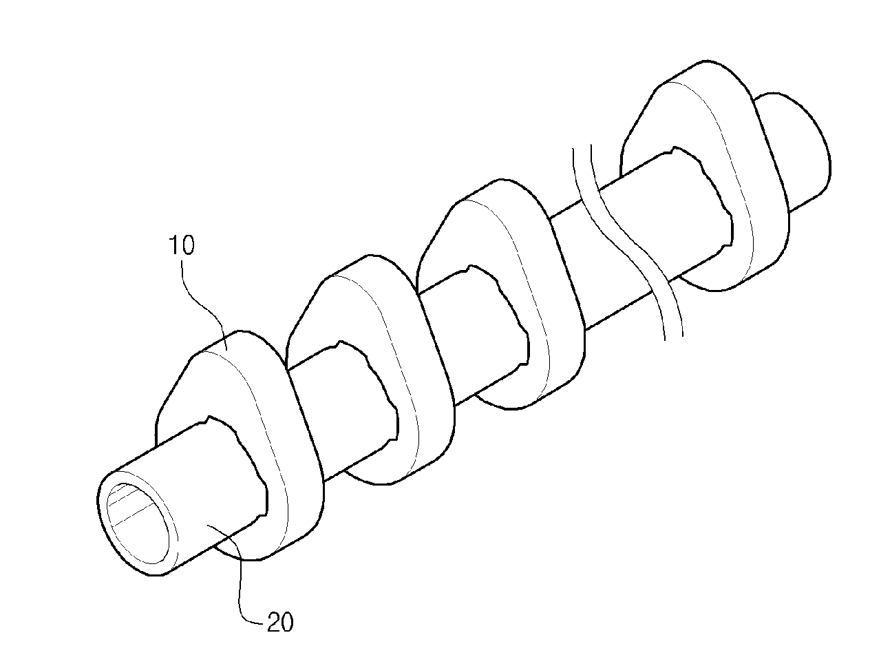
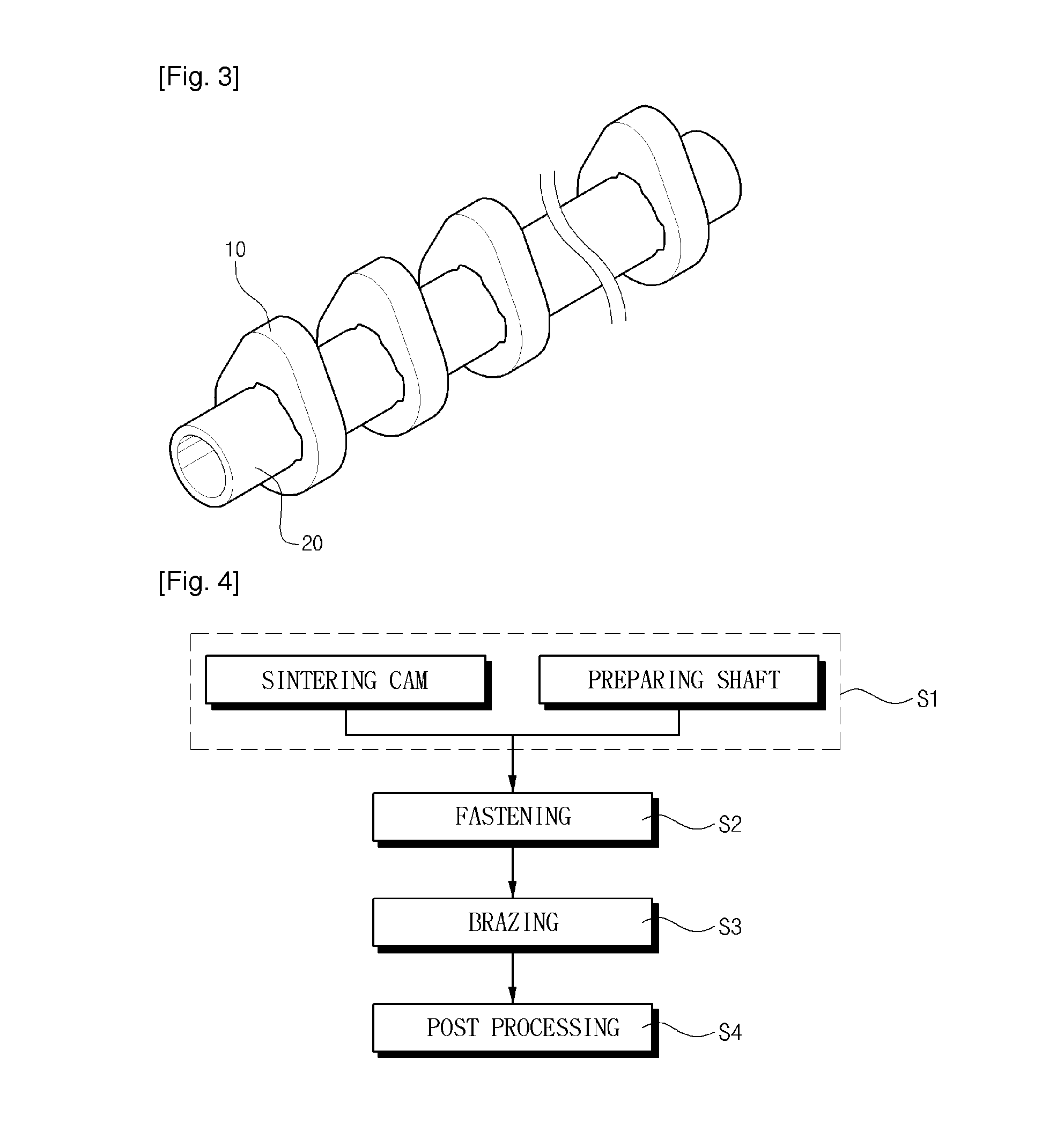
[0035]A method of manufacturing a camshaft according to the present invention includes manufacturing a cam 10 in which a depression 12 is formed, and fastening the cam 10 to a shaft 20 provided with a protrusion 21 in such a way that either the cam 10 or the shaft 20 is rotated relative to the other one. After the fastening, the cam 10 is joined with the shaft 20 by brazing rather than sintering.

[Manufacturing Cam Using Main-Sintering]

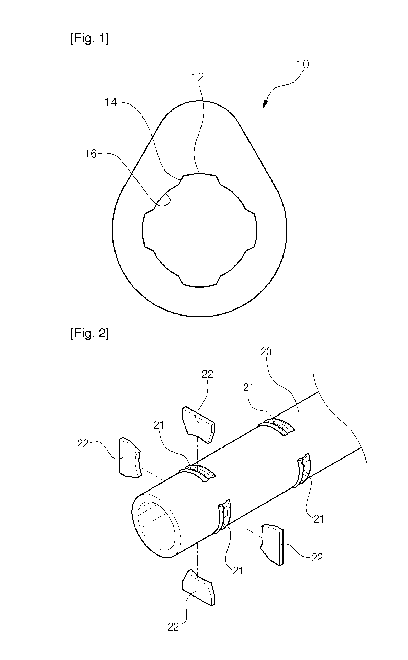
[0036]FIG. 1 illustrates a cam 10 having depressions 12 according to the present invention.

[0037]The circumferential inner surface of the cam 10 comprises depressions 12 which form a larger diameter, and small diameter portions 16. A ramp 14 is formed between each depression 12 and the adjacent small diameter portion 16.

[0038]The cam 10 having the depressions 12 is sintered after it has been formed. In the present inven...


PUM

PropertyMeasurementUnit
rotational forceaaaaaaaaaa
bonding strengthaaaaaaaaaa
durabilityaaaaaaaaaa

Abstract

Disclosed herein is a method of manufacturing a camshaft. Particularly, the present invention relates to a method of manufacturing a camshaft which includes a single sintering operation and a brazing operation, thus reducing the time for manufacturing.

Description

TECHNICAL FIELD[0001]The present invention relates, in general, to methods of manufacturing camshafts and, more particularly, to a method of manufacturing a camshaft which uses a brazing process, thus reducing the time for manufacturing.BACKGROUND ART[0002]Generally, a camshaft is provided with a plurality of cams which are provided on the shaft in different phases at positions spaced apart from each other at predetermined intervals. The camshaft is repeatedly rotated by rotational force of a crankshaft, thus periodically opening and closing an air-intake valve and an air-release valve of a combustion chamber so that the engine can be continuously operated.[0003]Such conventional camshafts are manufactured in an integrated rod type in which both a cam and a shaft are integrally formed of the same material, or in an assembly type in which a cam manufactured by a separate process is joined with a shaft in a variety of manners.[0004]The assembly type hollow camshaft can be lighter than...

Claims


Application Information

Patent Timeline
Patent Type & Authority Applications(United States)
IPC IPC(8): B23P15/00
CPCB23P2700/02B23P15/00B21J5/12B21K1/08B22F5/08B23K1/0008B23K2101/005B23K2103/04F01L1/047Y10T29/49293B21K1/06B22F5/00B23K1/00B23K31/02
Inventor KIM, YONG KYOONPARK, YUNG SANGSONG, JUN HOHAN, DONG KYUKIM, YOUNG HO
Owner SEOJIN CAM
Why Eureka
Try Eureka