Solar thermal air conditioning unit

a solar thermal and air conditioning technology, applied in the direction of refrigeration machines, household heating, refrigeration components, etc., can solve the problems of further air conditioning systems not producing hot water, drinking water, direct current,

Active Publication Date: 2014-08-14
RAHL STEVEN RICHARD
View PDF26 Cites 23 Cited by
  • Summary
  • Abstract
  • Description
  • Claims
  • Application Information

AI Technical Summary

Problems solved by technology

Currently, air conditioning systems consume a lot of energy.
Further air conditioning systems do not produce hot water, drinking water, or direct current.

Method used


Image

  • Solar thermal air conditioning unit
  • Solar thermal air conditioning unit
  • Solar thermal air conditioning unit

Examples


Embodiment Construction

[0015]The following detailed description is of the best currently contemplated modes of carrying out exemplary embodiments of the invention. The description is not to be taken in a limiting sense, but is made merely for the purpose of illustrating the general principles of the invention, since the scope of the invention is best defined by the appended claims.

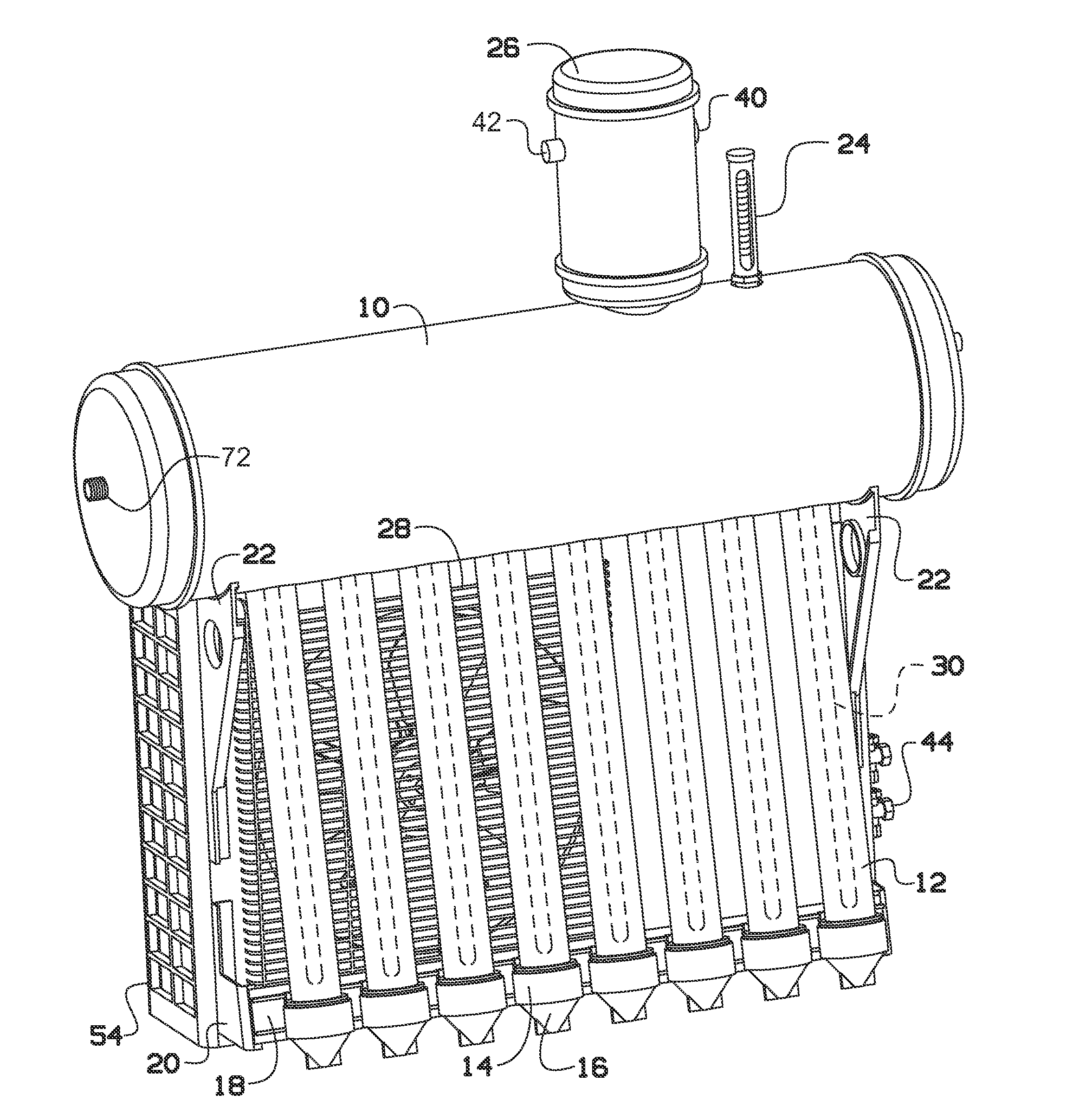
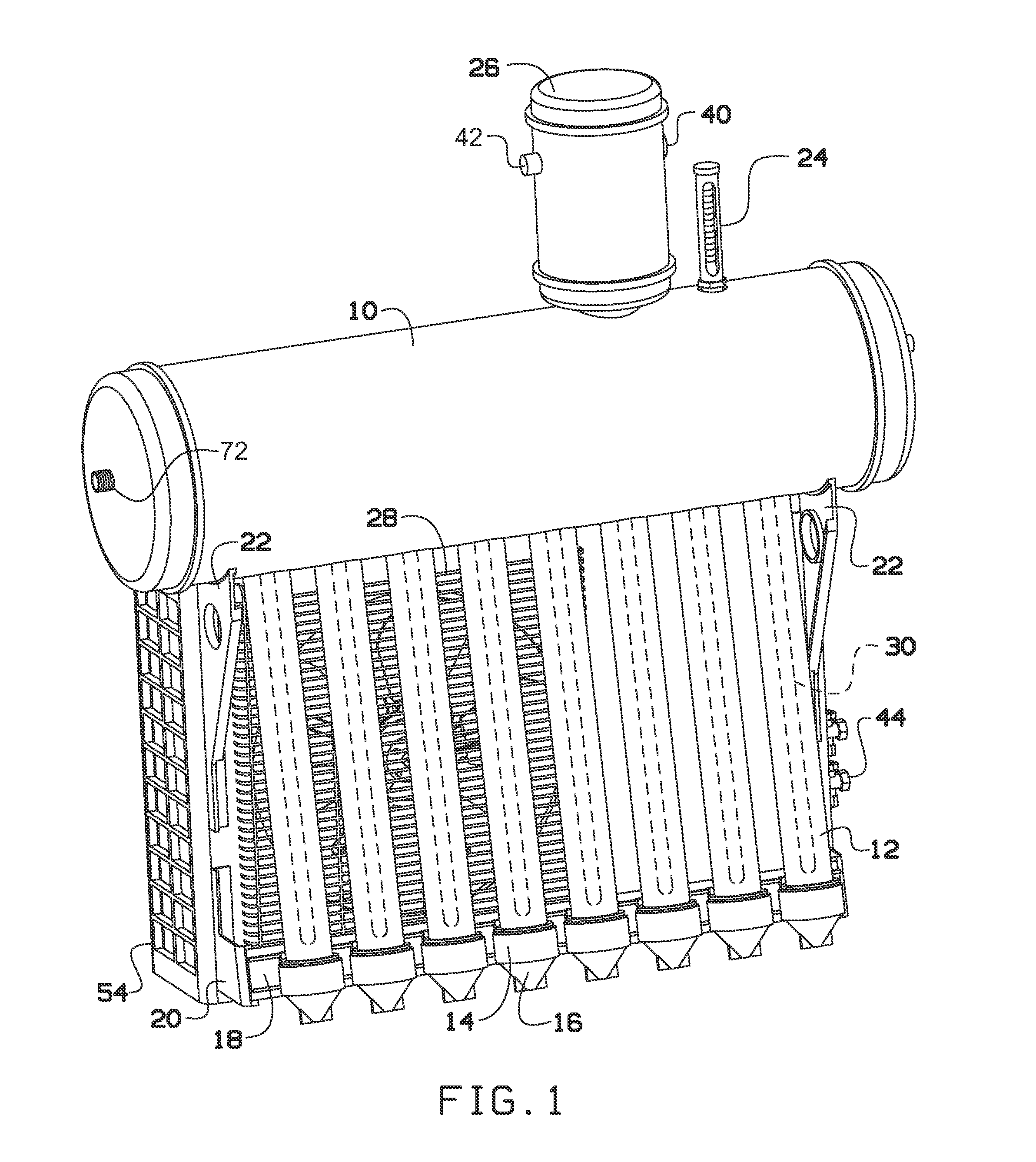
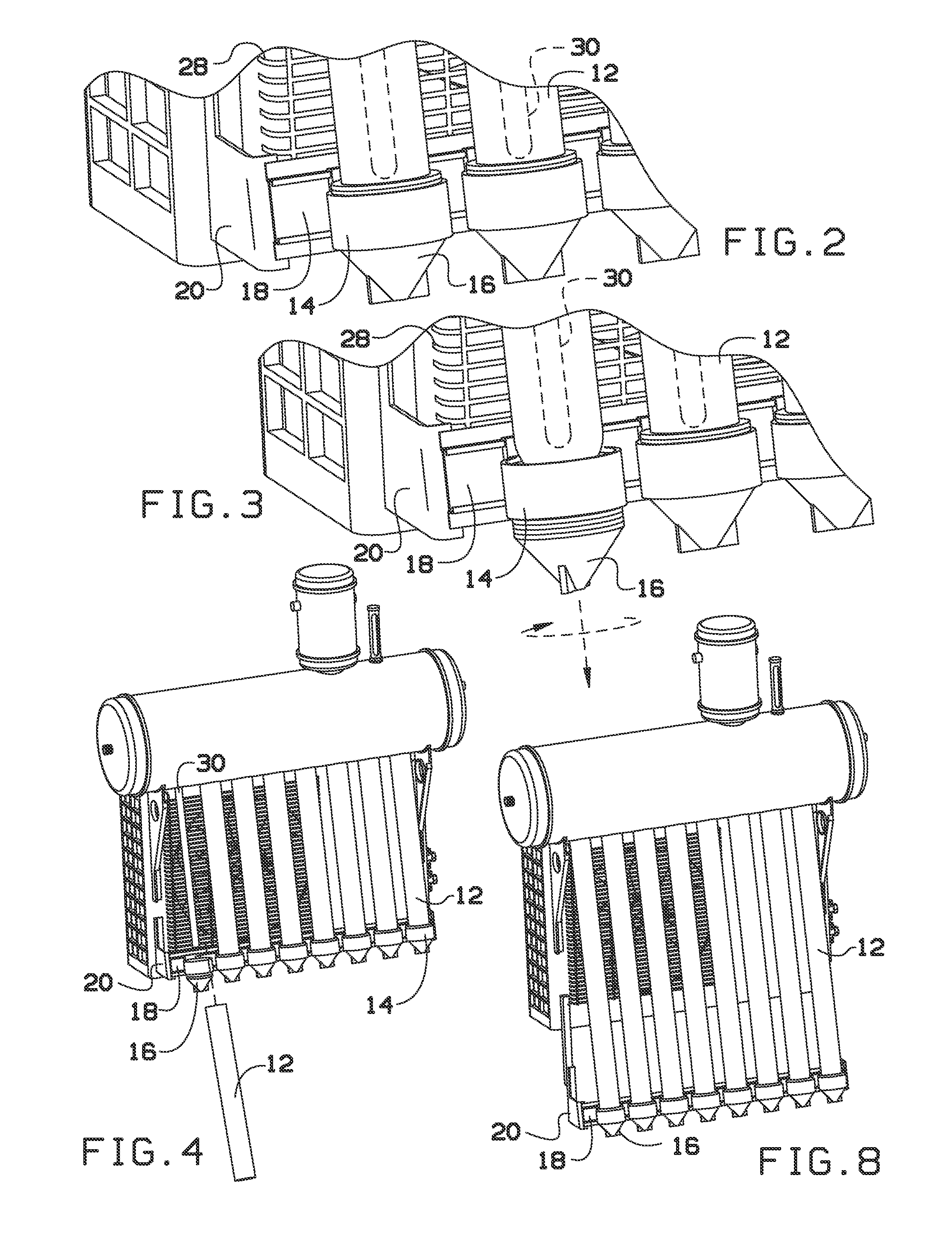
[0016]The present invention may include a thermal solar air-conditioner that absorbs solar energy from the sun, outside ambient temperatures, and a condenser to heat refrigerant, such as R410A, from a cold liquid to a hot vapor, by using vacuum solar collectors and copper rods for heat conduction. Further, the present invention may operate with dual condensers, dual capillaries, reverse heat valves, and hot and cold heat sinks with semi conductors producing electricity. The refrigerant from the compressor goes through the copper coiled inside a high density pressurized heated thermal tank, which undertakes a heat exchange. The r...


PUM


Abstract

A solar thermal air conditioning unit is provided. The solar thermal air condition unit includes a pressurized water tank with a water entrance port for receiving water. A copper coil tube may be within the pressurized water tank. The copper coiled tube may include a liquid refrigerant inlet and a gas refrigerant outlet. A solar heat converter may be connected to the pressurized water tank and may heat the water within the pressurized water tank, thereby heating the copper coil tube. The liquid refrigerant may be injected into the copper coil tube via the liquid refrigerant inlet and travels through the copper coil and is heated, thereby turning the liquid refrigerant to a gas refrigerant.

Description

CROSS-REFERENCE TO RELATED APPLICATION[0001]This application claims the benefit of priority of U.S. provisional application No. 61 / 762,679, filed Feb. 8, 2013, the contents of which are herein incorporated by reference.BACKGROUND OF THE INVENTION[0002]The present invention relates to a triple solar thermal air condition unit and, more particularly, to a water tank with an internal copper coil tubing configured to heat a liquid refrigerant to a gas refrigerant using solar energy.[0003]An air conditioner is a major or home appliance, system, or mechanism designed to change the air temperature and humidity within an area (used for cooling and sometimes heating depending on the air properties at a given time). The cooling is typically done using a simple refrigeration cycle, but sometimes evaporation is used, commonly for comfort cooling in buildings and motor vehicles. Currently, air conditioning systems consume a lot of energy. Further air conditioning systems do not produce hot water...

Claims


Application Information

Patent Timeline
Patent Type & Authority Applications(United States)
IPC IPC(8): F25B27/00F24S10/40F24S10/95
CPCF25B27/005F25B13/00F25B21/02F25B39/02F24F2005/0064F28F9/0234F28D1/0461F28D1/0477F28D15/0275F28D2020/0078Y02E10/44F24S60/30F24S2025/6005Y02A30/272F24S10/45F24S10/95Y02B10/20
Inventor RAHL, STEVEN RICHARD
Owner RAHL STEVEN RICHARD
Why Eureka
Try Eureka