
High velocity wind sonde

a high-speed wind and sonde technology, applied in the direction of fluid speed measurement, speed/acceleration/shock measurement, instruments, etc., can solve the problems of high cost of active steering technology, unfavorable wind speed determination, and change in cargo trajectory, so as to achieve high ballistic coefficient and high ballistic coefficient , the effect of rapid determination of wind velocity

Inactive Publication Date: 2014-08-14
HDT EXPEDITIONARY SYST
View PDF9 Cites 10 Cited by
  • Summary
  • Abstract
  • Description
  • Claims
  • Application Information

AI Technical Summary

Benefits of technology

This patent text describes a high ballistic coefficient wind sonde device that can detect and measure wind speed and direction relative to elevation. The device has a streamlined body with a tail that includes at least two fins, an electronic assembly for generating wind and altitude data, and a transmitting antenna for transmitting the data. The device can be used to predict the trajectory of cargo to be dropped from an aircraft. The technical effect of the patent is to provide a reliable and accurate tool for predicting wind speed and direction in high-altitude environments, which can aid in safely and efficiently dropping cargo from aircraft.

Problems solved by technology

However, after the cargo is discharged from the aircraft, environmental factors such as wind speed and wind direction may cause the cargo's trajectory to change and land at an undesired location.
However, these systems would be disadvantageous for cargo drops because they must maintain visual contact with the desired drop zone and would be inaccurate if clouds or other obstacles interrupt the signal of the trajectory path of the cargo.
However, this technology still requires costly active steering technology which includes actuators that control the fins and / or parachutes of the cargo.
This approach is costly and requires modifications to the aircraft, and may be less effective in certain weather conditions.
This information can be used to predict a trajectory of the cargo but it includes inaccuracies due to the slow sampling of raw data and the elapsed time.
A slowly descending wind sonde also reduces the efficiency and increases the risk of aerial delivery operations.
Even using another aircraft to drop the wind sonde is highly observable and increases the risk to the drop aircraft.

Method used


Image

  • High velocity wind sonde
  • High velocity wind sonde
  • High velocity wind sonde

Examples


Embodiment Construction

[0021]It is to be understood that the detailed figures are for purposes of illustrating exemplary embodiments of the present disclosure only and are not intended to be limiting. Additionally, it will be appreciated that the drawings are not to scale and that portions of certain elements may be exaggerated for the purpose of clarity and ease of illustration.

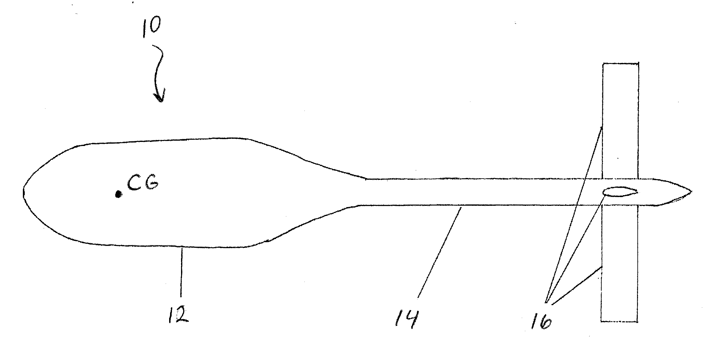
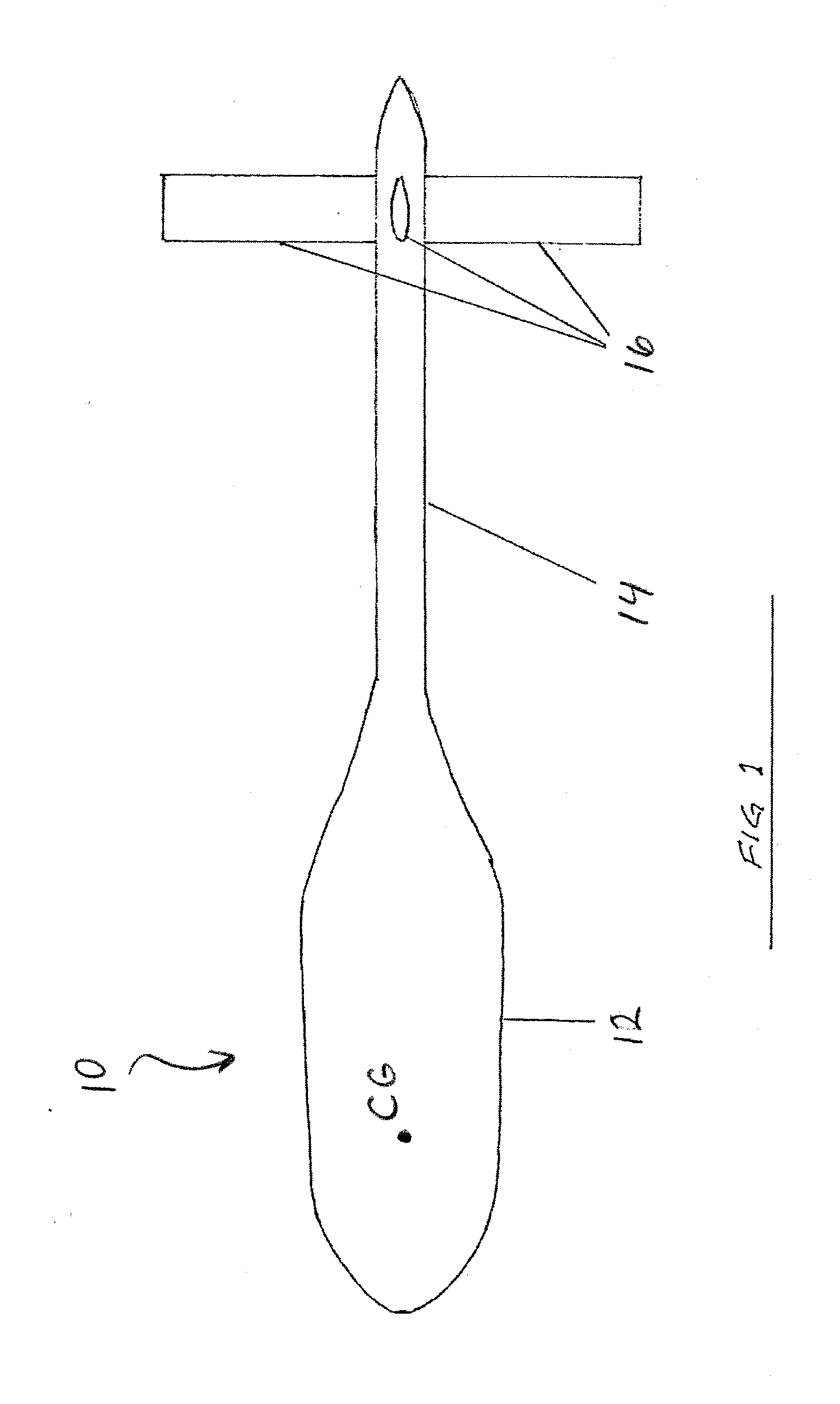
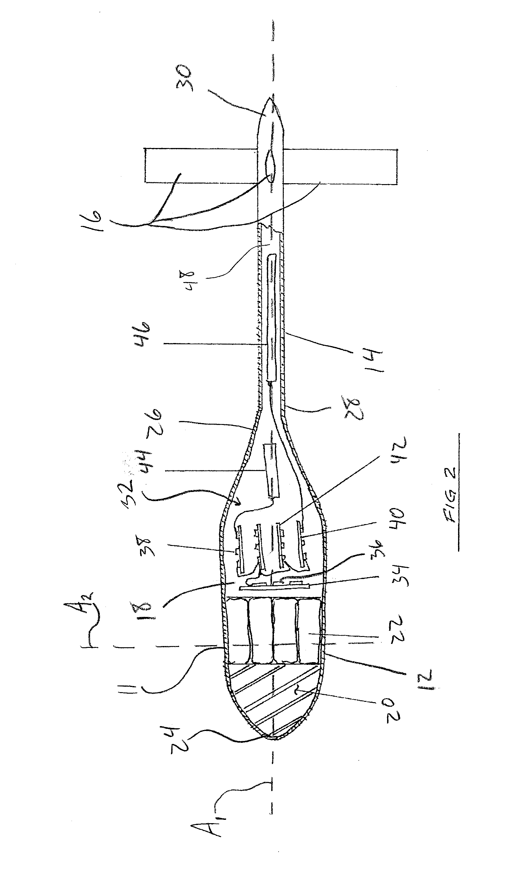
[0022]In accordance with the present disclosure, FIG. 1 illustrates the general configuration of a high ballistic coefficient wind sonde device 10 designed for receiving, sampling and transmitting wind and altitude data while traveling at a high velocity. The term “high ballistic coefficient” identifies that the device 10 travels quickly through the atmosphere. The wind sonde device 10 is designed to rely on the force of gravity to rapidly descend from an aircraft to the ground due to its aerodynamic shape and additional ballast as needed. The desired data sampled by the device 10 includes wind speed and wind direction as a functi...


PUM


Abstract

The present disclosure pertains to a high ballistic coefficient wind sonde device and a method of determining wind speed and wind direction measurements relative to altitude with a high velocity wind sonde device. The device includes a streamlined body including a first end, a second end, a longitudinal axis, and an internal cavity. A tail extension includes a first end that is connected to the body second end and a second end, wherein the tail extends along the longitudinal axis of the streamlined body. At least one pair of oppositely extending fins are mounted to the tail adjacent its second end. An electronic assembly is located in the internal cavity for generating wind and altitude data. A transmitting antenna is mounted to at least one of the body and the tail for transmitting the wind and altitude data generated by the electronic assembly.

Description

[0001]This application claims priority from the U.S. Provisional Application Ser. No. 61 / 764,253 filed on Feb. 13, 2013, the subject matter of which is incorporated hereinto in its entirety.BACKGROUND[0002]The present disclosure relates to a high ballistic coefficient wind sonde device for determining wind and altitude data. It finds particular application in conjunction with accurately dropping cargo from an aircraft into a desired drop zone, and will be described with particular reference thereto. However, it is to be appreciated that the present exemplary embodiment is also amenable to other like applications.[0003]It is a common maneuver to drop cargo from an aircraft while the aircraft is in use at an altitude above the ground with the intention that the cargo land in a desired drop zone. However, after the cargo is discharged from the aircraft, environmental factors such as wind speed and wind direction may cause the cargo's trajectory to change and land at an undesired locati...

Claims


Application Information

Patent Timeline
IPC IPC(8): G01W1/08
CPCG01W1/08G01P5/02G01P13/045
Inventor BROWN, GLEN J.
Owner HDT EXPEDITIONARY SYST
Learn More