
Lash adjuster

a technology of lash adjustment and lash, which is applied in the direction of valve arrangement, mechanical equipment, machines/engines, etc., can solve the problems of difficult fixation of partitioning members and air entrainment in high-level areas

Active Publication Date: 2014-08-14
OTICS CORP
View PDF2 Cites 7 Cited by
  • Summary
  • Abstract
  • Description
  • Claims
  • Application Information

AI Technical Summary

Benefits of technology

The invention is a lash adjuster that includes a partitioning member that can be fixed in a stable position within the plunger. The oil passage can be provided in the plunger without requiring a special structure, which improves design flexibility. The partitioning member can be easily assembled in the plunger and is stable during use. The oil passage is prevented from direct communication with the high-pressure chamber. These technical features make the lash adjuster more suitable for small-sized applications and reduce manufacturing costs and complexity.

Problems solved by technology

In this case, there is a possibility that air entrainment may occur in the high-pressure chamber when the hydraulic fluid level is low in the low-pressure chamber.
This reduces a press-fit allowance of the press-fit part particularly in small-sized lash adjusters, resulting in a problem that the partitioning member is difficult to fix in a stable state in the plunger.

Method used


Image

  • Lash adjuster
  • Lash adjuster
  • Lash adjuster

Examples


embodiment 2

[0039]FIG. 6 illustrates embodiment 2 of the invention.

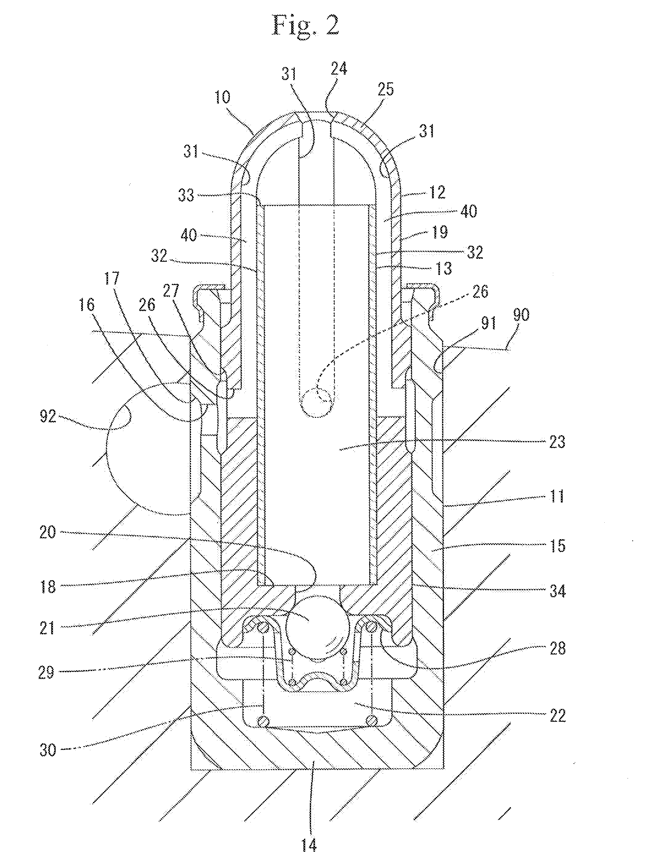
[0040]In embodiment 2, the peripheral wall 19 of the plunger 12 is formed with a single oil passage hole 26, and the inner periphery of the peripheral wall 19 is formed with a single recessed groove 31. A single oil passage 40 is defined between the groove face of the recessed groove 31 and the oil-passage defining portion 32 of the partitioning member 13. The recessed groove 31 and the oil passage 40 in embodiment 2 are similar to those in embodiment 1. That is, the recessed groove 31 and the oil passage 40 extend in the up-down direction and have respective lower ends communicating with the oil passage hole 26 and respective upper ends open to the through hole 24. The structure of the lash adjuster including the partitioning member 13 other than the above-described is similar to that in embodiment 1. Since the oil passage hole 26, the recessed groove 31 and the like in embodiment 2 have similar shapes to those in embodiment 1,...

embodiment 3

[0041]FIG. 7 illustrates embodiment 3.

[0042]In embodiment 3, three oil passage holes 26 are formed through the peripheral wall 19 of the plunger 12 circumferentially at intervals of 120°. Three recessed grooves 31 are formed in the inner periphery of the peripheral wall 19 circumferentially at intervals of 120°. The oil passage holes 26 and the recessed grooves 31 radially communicate with one another respectively. Furthermore, in the state where the partitioning member 3 is inserted in the plunger 12, three oil passages 40 are defined between the groove face of the recessed grooves 31 and the oil-passage defining portion 32. Embodiment 3 is similar to embodiment 1 in the other construction, and accordingly, identical or similar parts in embodiment 3 are labeled by the same reference symbols as those in embodiment 1.

[0043]The invention should not be limited to the foregoing embodiments and the following embodiments are included in the technical scope of the invention.

[0044](1) The r...


PUM


Abstract

A lash adjuster includes a body, a plunger which is inserted into the body and has a bottom wall with a valve hole and a peripheral wall having an oil passage hole and an inner periphery formed with a recessed groove, the plunger defining a high-pressure chamber between the bottom wall and the body, and a partitioning member inserted into the plunger. The partitioning member has an oil passage end located above the oil passage hole. The partitioning member has an oil-passage defining portion located opposite the recessed groove and defining an oil passage between itself and a groove face of the recessed groove. The partitioning member defines a low-pressure chamber inside. The low-pressure chamber reserves a hydraulic fluid flowing through the oil passage hole, the oil passage and the oil passage end. The low-pressure chamber causes the reserved hydraulic fluid to flow through the valve hole into the high-pressure chamber.

Description

CROSS-REFERENCE TO RELATED APPLICATIONS[0001]This application is based upon and claims the benefit of priority from the prior Japanese Patent Application No. 2013-26427 filed on Feb. 14, 2013, the entire contents of which are incorporated herein by reference.BACKGROUND[0002]1. Technical Field[0003]The present invention relates to a lash adjuster.[0004]2. Related Art[0005]A conventional lash adjuster includes a bottomed cylindrical body fixed to a cylinder head of an internal combustion engine and a plunger which is inserted into the body so that the plunger is movable up and down. The plunger has an upper end supporting a rocker arm. The plunger further has a peripheral wall formed with an oil passage hole and a bottom wall formed with a valve hole. Hydraulic fluid, such as oil, supplied through an oil filler hole of the cylinder head is stored in a low-pressure chamber in the plunger through the oil passage hole and also supplied through the valve hole into the body thereby to fill...

Claims


Application Information

Patent Timeline
Patent Type & Authority Applications(United States)
IPC IPC(8): F01L1/24
CPCF01L1/24F01L1/2405F01L1/255F01L2001/2427F01L2001/256
Inventor SUZUKI, HIROYUKIOKA, HIDEKIMASEGI, KIYOSHI
Owner OTICS CORP
Learn More