Control unit of internal combustion engine equipped with supercharger

a technology of control unit and internal combustion engine, which is applied in the direction of electric control, combustion engine, machines/engines, etc., can solve the problems of large gap between required torque and current torque, insufficient current torque for the required torque, and driver's inability to get the expected feeling of deceleration, so as to reduce the engine output torque

Inactive Publication Date: 2014-08-14
TOYOTA JIDOSHA KK
View PDF0 Cites 8 Cited by
  • Summary
  • Abstract
  • Description
  • Claims
  • Application Information

AI Technical Summary

Benefits of technology

[0019]Setting the target torque as described above makes it possible to decrease the engine output torque in accordance with the release operation of the accelerator pedal performed by the driver. By this, the torque reduction which the driver requests to the internal combustion engine via the operation of the accelerator pedal is achieved, and a desired feeling of deceleration is given to the driver. In this case, it is more preferable to set a target amount of decreas

Problems solved by technology

However, in this case, there exist the following issues which are peculiar to the supercharged internal combustion engine.
In the case of the supercharged internal combustion engine, a situation where there is a large gap between the required torque and a current torque persists for a while from a start of acceleration due to a response delay of an air quantity caused by a supercharger.
However, in the situation wh

Method used


Image

  • Control unit of internal combustion engine equipped with supercharger
  • Control unit of internal combustion engine equipped with supercharger
  • Control unit of internal combustion engine equipped with supercharger

Examples


first embodiment

[0027]The first embodiment of the present invention will be described with reference to the drawings.

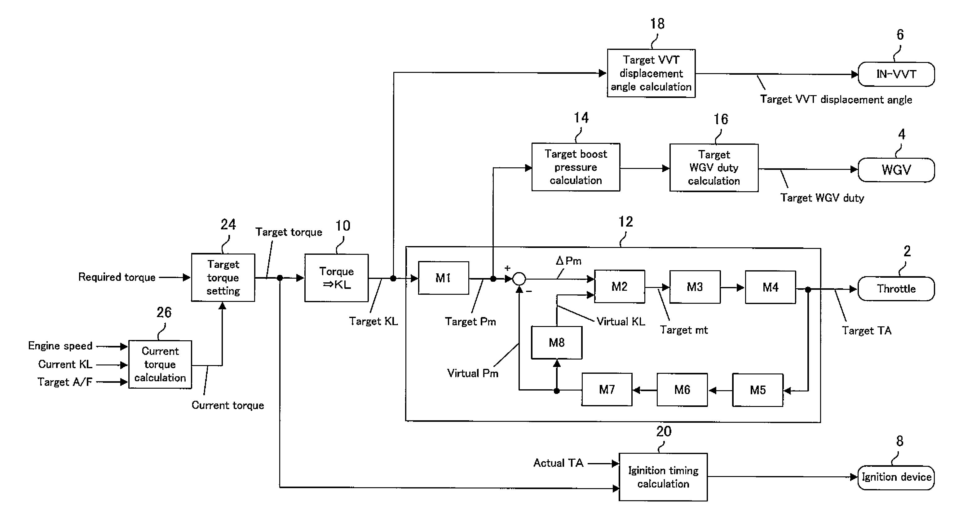
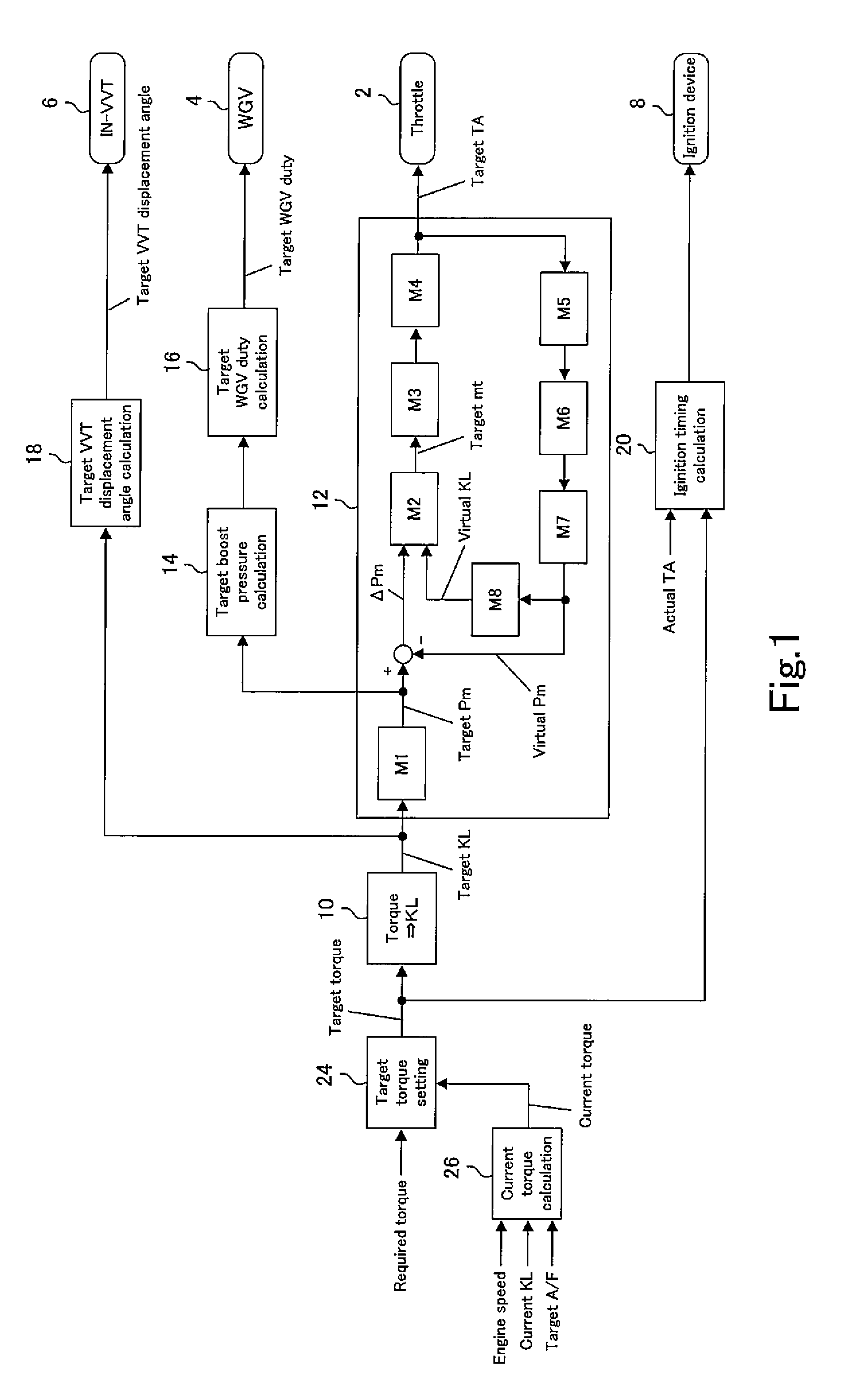
[0028]An internal combustion engine which the control unit of the present embodiment is applied to is a supercharged internal combustion engine for a vehicle, in particular, a spark ignition type four-cycle reciprocal engine equipped with a turbocharger, in more detail, an internal combustion engine having an electronic-controlled throttle (hereinafter referred to as throttle simply), a variable valve timing apparatus changing valve timing of an intake valve (hereinafter referred to as IN-VVT), and a waste gate valve (hereinafter referred to as WGV). The control unit is implemented as a function of an ECU (Electronic control unit) which is provided to the internal combustion engine. For details, the ECU functions as the control unit when a program stored in a memory is executed by a CPU. When the ECU functions as the control unit, the ECU controls the operation of each actuator inclu...

second embodiment

[0057]Next, the second embodiment of the present invention will be described with reference to the drawings.

[0058]FIG. 5 is a functional block diagram showing a configuration of the control unit of the second embodiment of the present invention. The control unit of the second embodiment corresponds to a partially modified configuration of that of the first embodiment. Therefore, among the elements constituting the control unit of the second embodiment, the elements having functions common to that of the first embodiment are assigned with the same reference numerals in the figure. Hereinafter, whereas describing functions in common with the first embodiment will be simplified or omitted, the configuration of the control unit of the second embodiment will be described with a focus on functions different from the first embodiment.

[0059]The difference between the control unit of the second embodiment and that of the first embodiment is in a torque value used for setting respective targe...

third embodiment

[0063]Next, the third embodiment of the present invention will be described with reference to the drawings.

[0064]FIG. 7 is a functional block diagram showing a configuration of the control unit of the third embodiment of the present invention. The control unit of the third embodiment corresponds to a partially modified configuration of that of the second embodiment. Therefore, among the elements constituting the control unit of the third embodiment, the elements having functions common to that of the second embodiment are assigned with the same reference numerals in the figure. Hereinafter, whereas describing functions in common with the second embodiment will be simplified or omitted, the configuration of the control unit of the third embodiment will be described with a focus on functions different from the second embodiment.

[0065]The difference between the control unit of the third embodiment and that of the second embodiment is in a torque value used for setting respective target...


PUM


Abstract

According to the present invention, torque controllability may be improved in a situation in which there is a gap between a required torque and a current torque based on a supercharge delay of a supercharger when calculation of a target throttle divergence using an air reverse model is applied to a supercharged internal combustion engine. Although the control unit of the present invention usually determines the required torque as a target torque, the control unit determines a value lower than the current torque when a reduction direction change occurs in the required torque while there is the gap between the required torque and the current torque. Desirably, the control unit determines a target torque reduction correspondingly to a decrease in the required torque, and determines a target torque reduction subtracted from the current torque as the target torque. The control unit calculates a target air volume from the determined target torque, and calculates the target throttle divergence by using the air reverse model and based on the target air volume.

Description

TECHNICAL FIELD[0001]The present invention relates to a control unit of a supercharged internal combustion engine which has a throttle. More specifically, the present invention relates to a control unit of a supercharged internal combustion engine which is configured to calculate a target throttle opening based on a target air quantity with use of an air inverse model.BACKGROUND ART[0002]A method of setting a target throttle opening by calculation with use of an air inverse model is known as disclosed in Japanese Patent Laid-Open No. 2010-053705. The air inverse model is an inverse model of an air model in which a response of an air quantity to an operation of a throttle is modeled and is expressed in mathematical form. A throttle opening required to achieve a required torque is calculated by calculating a target air quantity from the required torque and inputting it into the air inverse model.[0003]Calculation procedure of the target throttle opening with use of the air inverse mod...

Claims


Application Information

Patent Timeline
IPC IPC(8): F02D23/02
CPCF02D23/02F02D41/0007F02D2041/1434F02D2200/0402F02D2250/21F02D13/0234Y02T10/12
Inventor YOSHIZAKI, SATOSHITAKAHASHI, KIYONORISHIBAYAMA, MASASHI
Owner TOYOTA JIDOSHA KK
Why Eureka
Try Eureka