Peak cut system

a technology of a cut system and a power storage device, which is applied in the direction of load forecasting in ac networks, electric power transfer ac networks, ac network load balancing, etc., can solve the problems of excessive power charging to power storage devices and excessive power charging, so as to reduce the power generation of power-generating devices, increase the running cost of power-generating devices, and increase fuel costs

Inactive Publication Date: 2014-08-14
TOSHIBA MITSUBISHI-ELECTRIC IND SYST CORP
View PDF20 Cites 5 Cited by
  • Summary
  • Abstract
  • Description
  • Claims
  • Application Information

AI Technical Summary

Benefits of technology

[0011]The peak cut system according to the present invention includes a load, a power system which carries out power supply to the load, a power-generating device which generates power and supplies the generated power to the load, a power storage device which carries out charge and discharge with respect to the load, and a control unit which controls the power supply to the load, wherein the control unit executes a first peak cut process which carries out peak cut with respect to power received from the power system by executing the discharge from the power storage device, and executes a second peak cut process which carries out the peak cut by carrying out the power generation by the power-generating device only when a predetermined amount of peak cut cannot be achieved only by the discharge from the power storage device.
[0012]Accordingly, in the present invention, for the peak cut process, the power generation by the power-generating device can be minimized always without the power generation by the power-generating device. Therefore, the peak cut system according to the present invention can prevent the power generation by the power-generating device even when the peak cut process is carried out in the case of increasing the running cost of the power-generating device due to the higher fuel cost. That is, the peak cut system can reduce the running cost of the power-generating device.
[0013]The object, features, aspects, and advantages of the present invention will be more apparent with reference to the following detailed description and the accompanying drawings.

Problems solved by technology

In addition, in a technique according to Patent Document 2, when power consumed by a load is increased, after the discharge of power which is previously charged to efficiently operate a power-generating device, a first self-generating device is started so that excessive power is charged to a power storage device while the power is outputted to the load.
Further, after the start of the second self-generating device, excessive power is charged to the power storage device while the power is outputted to the load.

Method used


Image

  • Peak cut system
  • Peak cut system
  • Peak cut system

Examples


embodiment

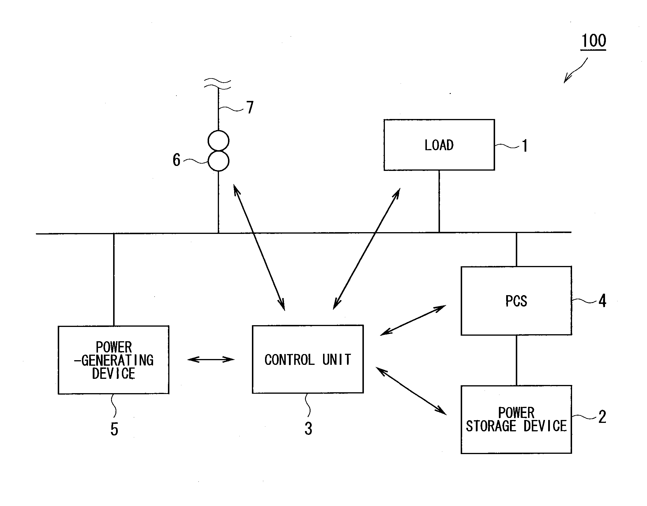
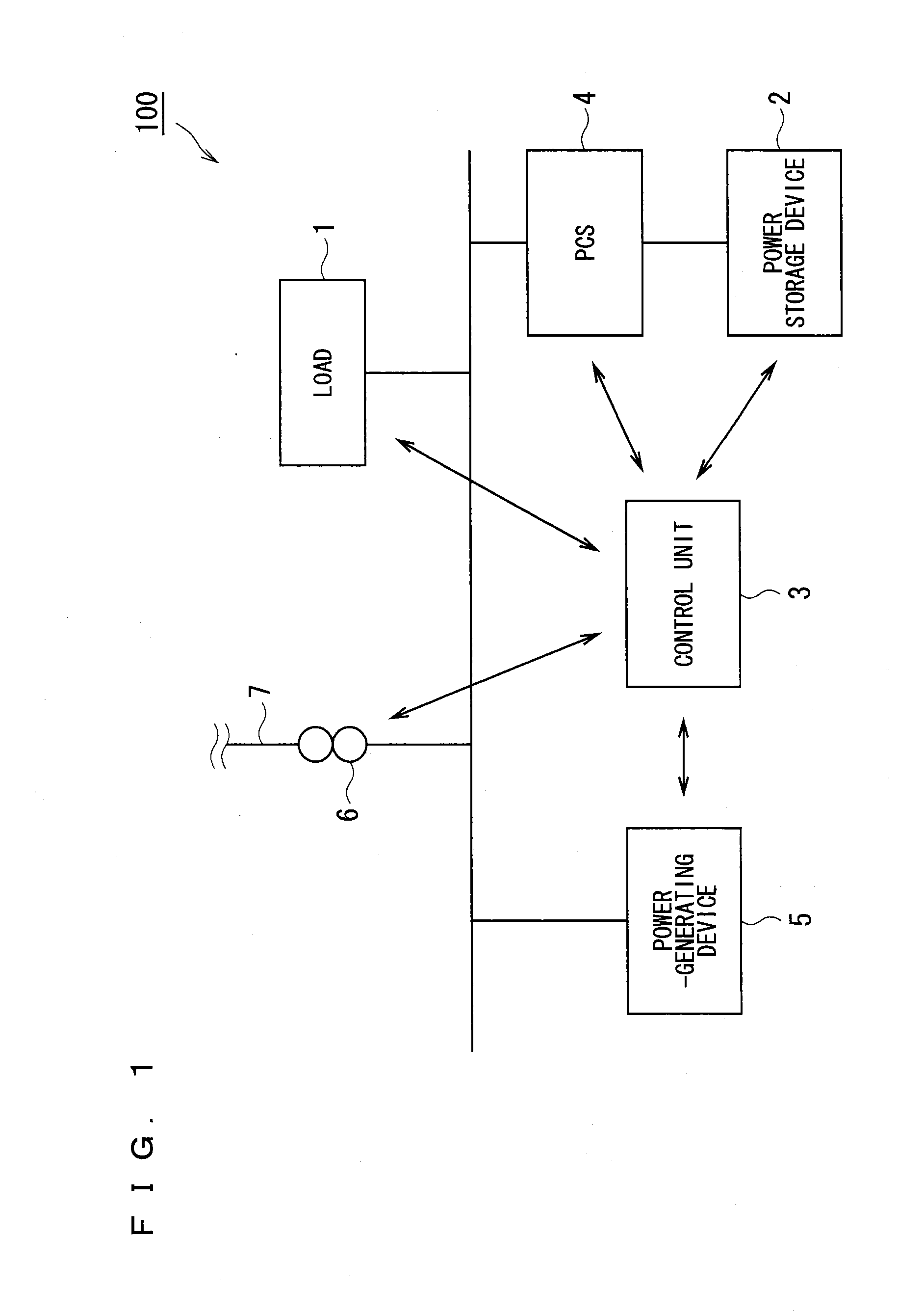
[0025]FIG. 1 is a schematic diagram showing the configuration of a peak cut system 100 according to the embodiment of the present invention.

[0026]As shown in FIG. 1, the peak cut system 100 according to this embodiment includes a load 1, a power storage device 2, a control unit 3, a PCS (Power Conditioning Subsystem) 4, a power-generating device 5, a power receiving unit 6, and a power system 7.

[0027]The load 1 is installed in an electrical system on the demander side. The load 1 is an electric device including electrical equipment and the like operated with power supply, and is installed in a plant and a building and the like. In FIG. 1, only one load 1 is shown, but a plurality of loads 1 may be installed. In addition to power supply from the power system 7, the load 1 can receive the supply of power which is discharged from the power storage device 2, and can receive the supply of power generated by the power-generating device 5.

[0028]The power system 7 is a power generation, tra...


PUM


Abstract

A peak cut system which can reduce the running cost of a power-generating device even when a peak cut process is carried out. In a peak cut system, a control unit executes such a control procedure that a peak cut process is first carried out only by the discharge from a power storage device and the power generation by a power-generating device is carried out only when a predetermined amount of peak cut cannot be achieved only by the discharge from the power storage device.

Description

TECHNICAL FIELD[0001]The present invention relates to a peak cut system in cooperation with a power system, which carries out peak cut with respect to power received from the power system.BACKGROUND ART[0002]To carry out peak cut with respect to power received from a power system, a self-generating system in cooperation with the power system has been introduced (for instance, Patent Documents 1 and 2).[0003]In a technique according to Patent Document 1, a convertor carries out conversion to charge power generated by a power-generating device and / or power supplied from a power system to a secondary battery or to supply power generated by the power-generating device and power which is discharged from the secondary battery, to a load. A controller controls the operation of the secondary battery so that the total of the power generated by the power-generating device and the power which is discharged from the secondary battery is not below power consumption of the load which exceeds a pe...

Claims


Application Information

Patent Timeline
Patent Type & Authority Applications(United States)
IPC IPC(8): H02J4/00
CPCH02J4/00H02J3/32H02J3/38H02J3/34H02J3/003
Inventor HANADA, MASATO
Owner TOSHIBA MITSUBISHI-ELECTRIC IND SYST CORP
Why Eureka
Try Eureka