Voltage converter

a voltage converter and converter technology, applied in the field of voltage converters, can solve problems such as degrading the quality of the buck output voltage vout, and achieve the effect of improving the quality of the output signal generated

Active Publication Date: 2014-08-14
EXCELLIANCE MOS
View PDF14 Cites 6 Cited by
  • Summary
  • Abstract
  • Description
  • Claims
  • Application Information

AI Technical Summary

Benefits of technology

[0017]Based on the above, in the present invention, the ripple injection circuit gets the voltage of the feedback end and the voltage of the phase end of the voltage converter to generate the injection signal, and provides the injection signal to the constant on time signal generator. The constant on time signal generator generates the first and the second driving signals according to the injection signal, the output signal and the reference signal. In this way, the output signal generated by the voltage converter has a steady ripple component, thereby improving the quality of the output signal generated by the voltage converter.

Problems solved by technology

The ripple component on the feedback signal VFB will become very unobvious, which incurs an unsteady ripple phenomenon on the buck output voltage VOUT, degrading the quality of the buck output voltage VOUT.

Method used


Image

  • Voltage converter
  • Voltage converter
  • Voltage converter

Examples


Embodiment Construction

[0025]Reference will now be made in detail to the present embodiments of the invention, examples of which are illustrated in the accompanying drawings. Wherever possible, the same reference numbers are used in the drawings and the description to refer to the same or like parts.

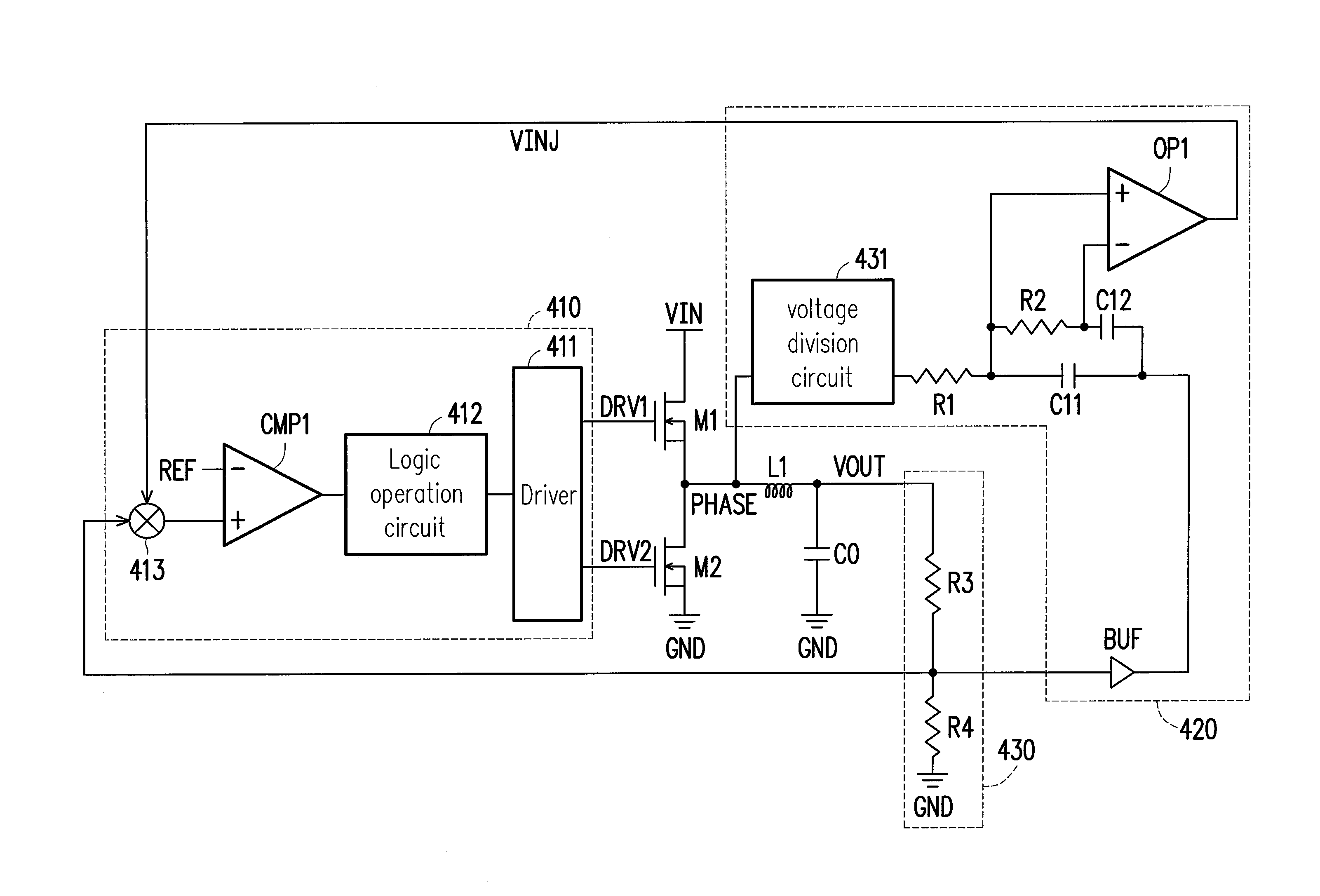
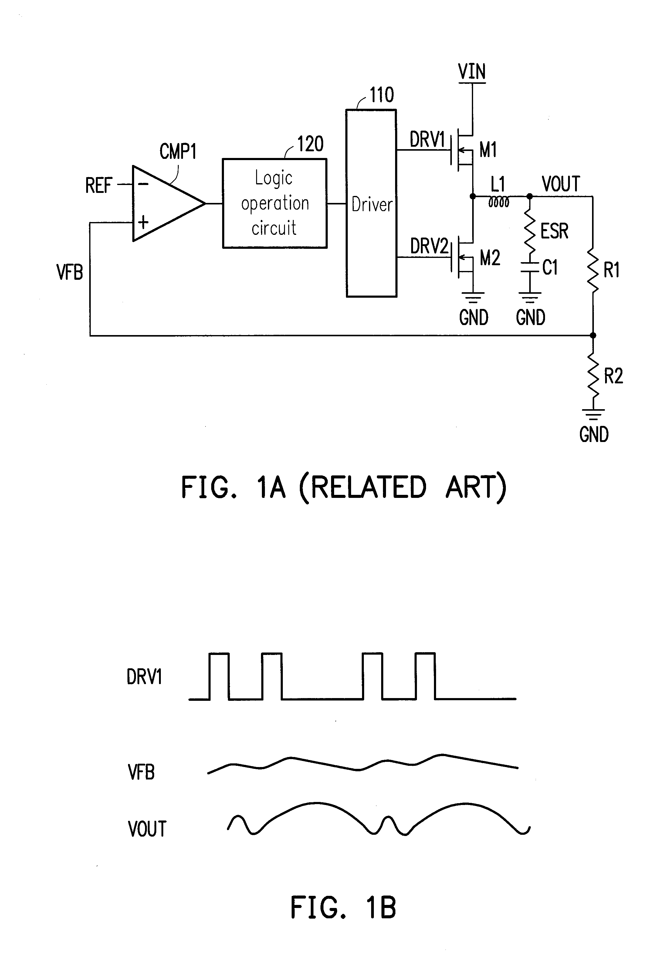
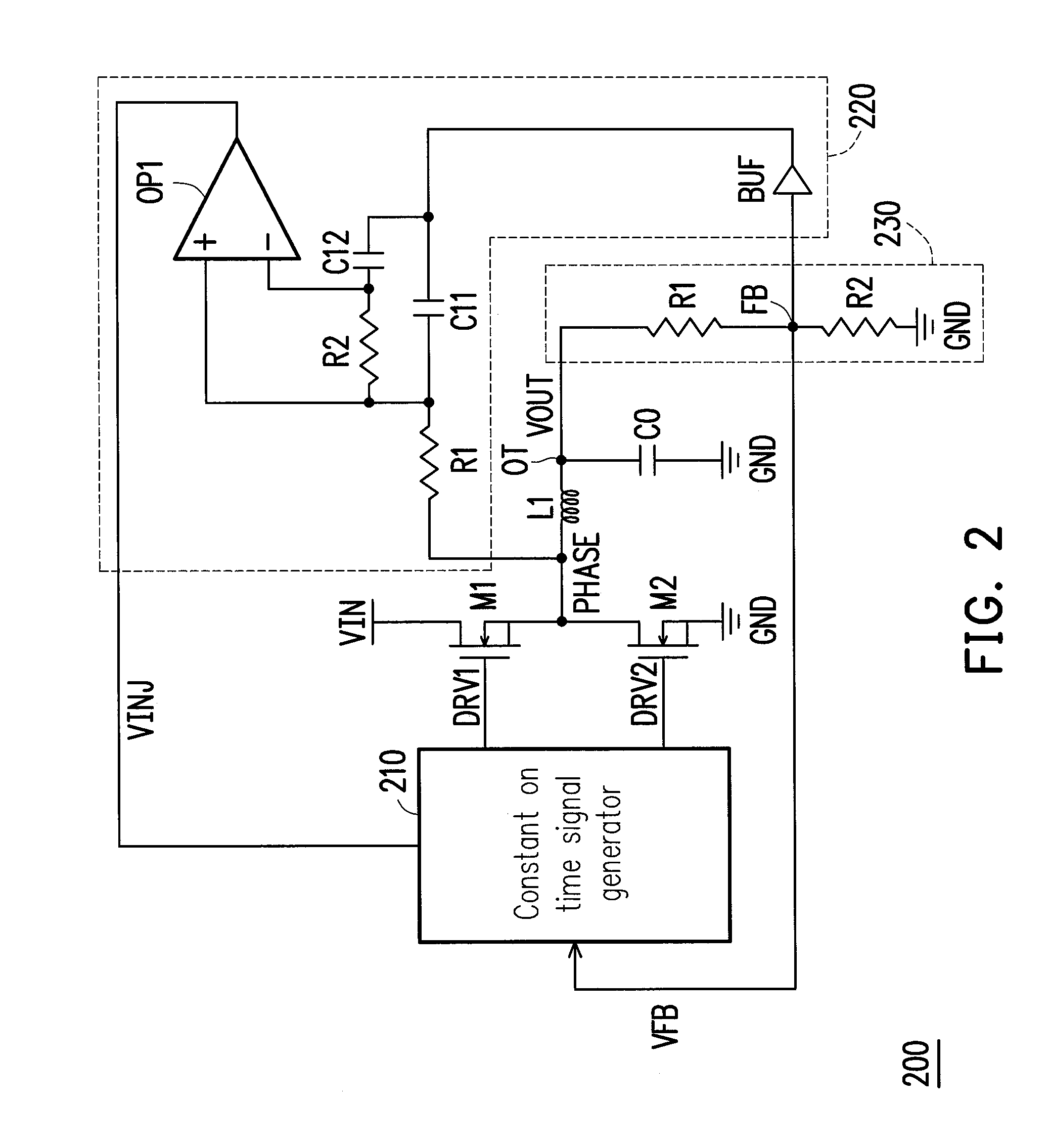
[0026]FIG. 2 is a schematic view of a voltage converter 200 according to an embodiment of the present invention. Referring to FIG. 2, the voltage converter 200 is a buck-type voltage converter. The voltage converter 200 includes a constant on time signal generator 210, transistors M1 and M2, an inductor L1, a ripple injection circuit 220 and a feedback circuit 230. The constant on time signal generator 210 generates driving signals DRV1 and DRV2. The transistor M1 has a first end for receiving a power supply voltage VIN, a second end coupled to a phase end PHASE of the voltage converter 200, and a control end for receiving the driving signal DRV1. Likewise, the transistor M2 has a first end coupled to the phas...


PUM


Abstract

A voltage converter is disclosed. The voltage converter includes a constant on time signal generator, a first and second transistors, an inductor, a feedback circuit and a ripple injection circuit. The constant on time signal generator generates a first and second driving signals for driving the first and second transistors. The voltage converter generates an output signal at an output end thereof. The feedback circuit divides the output signal to generate a feedback signal at a feedback end of the voltage converter. The ripple injection circuit gets the voltage of the feedback end and the voltage of the phase end to generate a injection signal. The constant on time signal generator generates the first and second driving signals according to the injection signal, the output signal and a reference signal.

Description

BACKGROUND OF THE INVENTION[0001]1. Field of the Invention[0002]The present invention generally relates to a voltage converter, in particular, to a buck-type voltage converter capable of generating an output signal having a steady ripple.[0003]2. Description of Related Art[0004]FIG. 1A shows a conventional voltage converter 100. Referring to FIG. 1A, the voltage converter 100 includes a driver 110, a logic operation circuit 120, a comparator CMP1, transistors M1 and M2, an inductor L1, a capacitor C1 and resistors R1 and R2. In the voltage converter 100, the comparator CMP1 compares a reference signal REF with a feedback signal VFB to generate a comparison result, which is processed by the logic operation circuit 120 and the driver 110 in sequence to generate driving signals DRV1 and DRV2. In addition, the transistor M1 receives a power supply voltage VIN.[0005]In the voltage converter 100, when the comparator CMP1 determines through comparison that the feedback signal VFB is lower ...

Claims


Application Information

Patent Timeline
Patent Type & Authority Applications(United States)
IPC IPC(8): G05F1/445
CPCG05F1/445H02M3/156H02M1/0025
Inventor LIN, PAO-CHUANCHEN, LI-CHIEHCHOU, HUNG-CHE
Owner EXCELLIANCE MOS
Why Eureka
Try Eureka