
Signal amplification circuit

a signal amplification and circuit technology, applied in the direction of amplifiers with semiconductor devices/discharge tubes, digital storage, differential amplifiers, etc., can solve the problems of data inability to be fully balanced, data quality is inevitably attenuated, and current consumption of semiconductor memory devices may additionally increase, so as to improve the quality of output signals and simple configuration

Active Publication Date: 2014-11-18
SK HYNIX INC
View PDF2 Cites 3 Cited by
  • Summary
  • Abstract
  • Description
  • Claims
  • Application Information

AI Technical Summary

Benefits of technology

The present invention is a circuit that can control the amount of electric current that flows through it based on the impulse signal that it produces. This helps to improve the quality of the output signal produced by the circuit, without needing a complex and expensive setup.

Problems solved by technology

Therefore, during the high-frequency operation, data are inevitably attenuated to some extent.
Accordingly, since the voltage difference between the reference voltage and the input signal decreases due to the above-described attenuation during the high-frequency operation, the quality of the output signal of the input buffer circuit may deteriorate.
However since the equalization circuit includes a plurality of logic gates and the like, the current consumption of the semiconductor memory device additionally increases, and the size of the semiconductor memory device significantly increases.

Method used


Image

  • Signal amplification circuit
  • Signal amplification circuit
  • Signal amplification circuit

Examples


Embodiment Construction

[0019]Exemplary embodiments of the present invention will be described below in more detail with reference to the accompanying drawings. The present invention may, however, be embodied in different forms and should not be construed as limited to the embodiments set forth herein. Rather, these embodiments are provided so that this disclosure will be thorough and complete, and will fully convey the scope of the present invention to those skilled in the art. Throughout the disclosure, reference numerals correspond directly to the like numbered parts in the various figures and embodiments of the present invention. It is also noted that in this specification, “connected / coupled” refers to one component not only directly coupling another component but also indirectly coupling another component through an intermediate component. In addition, a singular form may include a plural form as long as it is not specifically mentioned in a sentence.

[0020]In the following descriptions, sourcing a cu...


PUM


Abstract

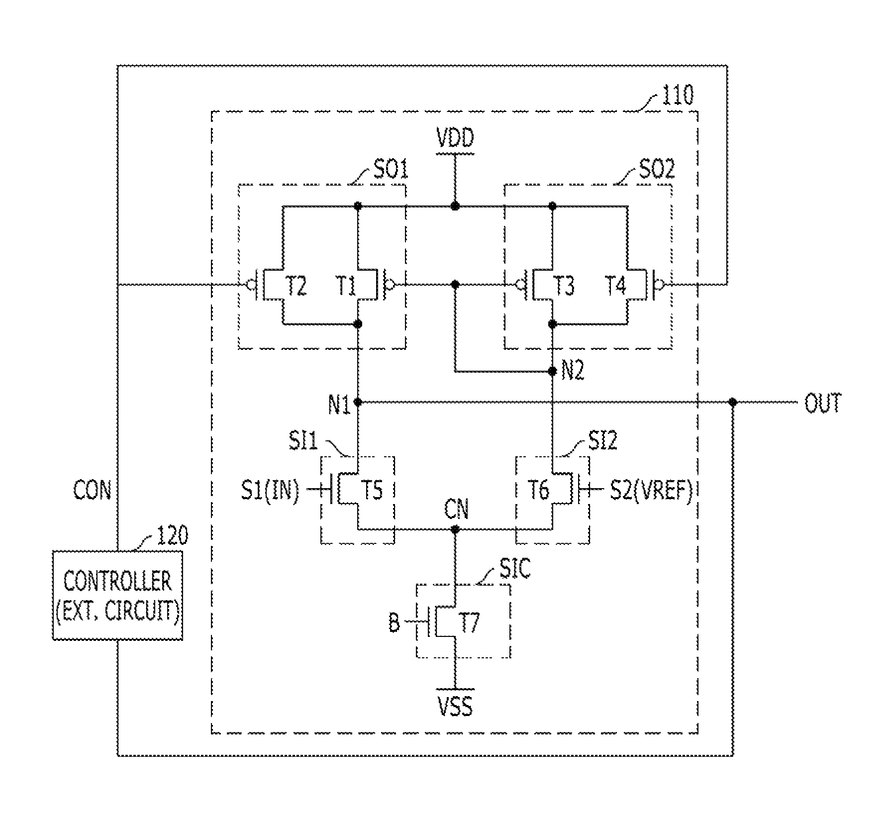
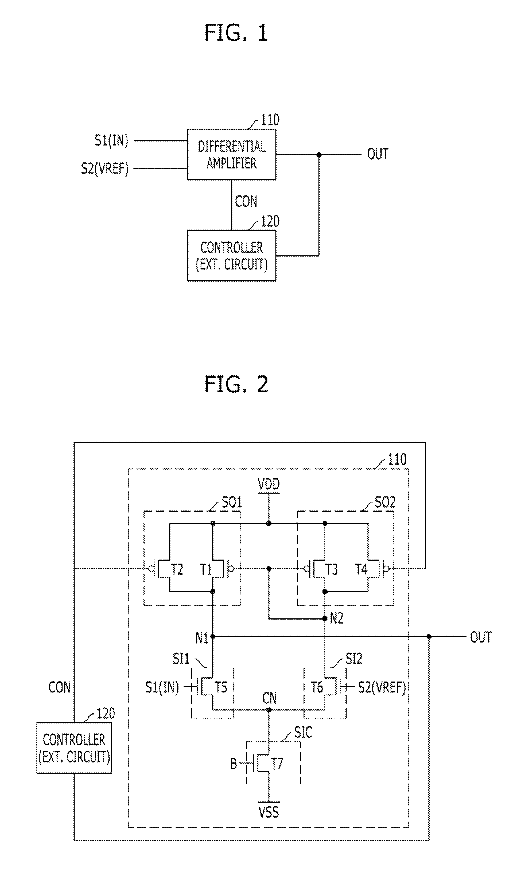
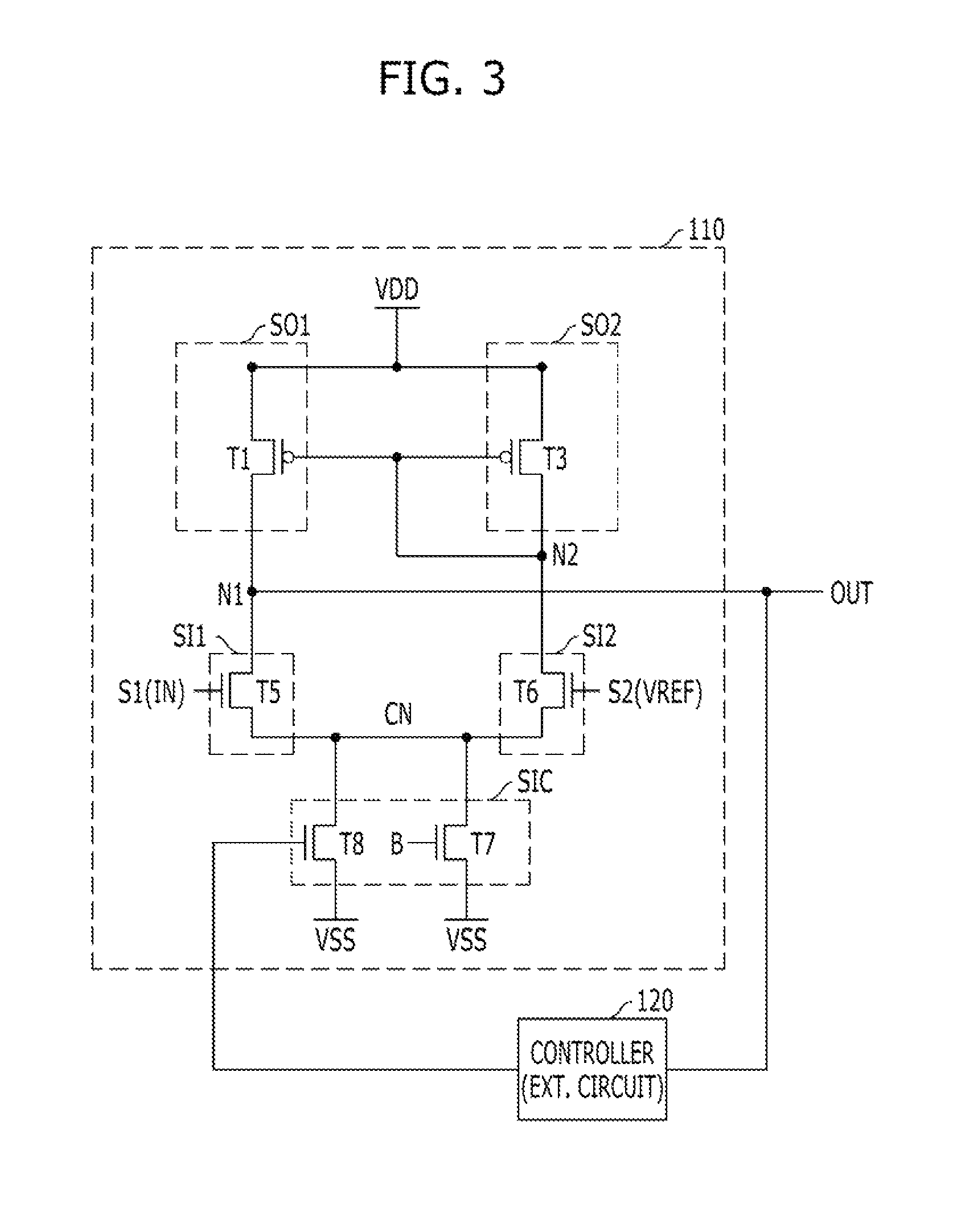
A signal amplification circuit includes a differential amplifier configured to receive a first signal and a second signal and generate an output signal, a differential amplifier configured to receive first and second signals and generate an output signal; and a controller configured to control an amount of current flowing in the differential amplifier using the output signal.

Description

CROSS-REFERENCE TO RELATED APPLICATIONS[0001]The present application claims priority of Korean Patent Application No. 10-2011-0140370 filed on Dec. 22, 2011, which is incorporated herein by reference in its entirety.BACKGROUND[0002]1. Field[0003]Exemplary embodiments of the present invention relate to a signal amplification circuit.[0004]2. Description of the Related Art[0005]In order to store data in the semiconductor memory device, an input buffer circuit for receiving data from another device is used. The input buffer circuit receives data from an external electronic element or electronic device, amplifies the received data, and converts the amplified data into a level which may be processed by the semiconductor memory device for example, a CMOS level.[0006]Examples of circuits used as the input buffer circuit of the semiconductor memory device may include a differential amplifier circuit using a current mirror. Here, the differential amplifier circuit refers to an amplifier whic...

Claims


Application Information

Patent Timeline
Patent Type & Authority Patents(United States)
IPC IPC(8): H03F3/45
CPCH03F2203/45641H03F2203/45466H03F2203/45674H03F2203/45166H03F3/45183H03F3/45076H03F2203/45248G11C7/10H03K19/0175
Inventor HWANG, TAE-JIN
Owner SK HYNIX INC
Learn More