Rotation angle measurement apparatus

a measurement apparatus and rotational angle technology, applied in the direction of instruments, galvano-magnetic hall-effect devices, galvano-magnetic devices, etc., can solve problems such as errors in calculated angles, and achieve the effect of preventing accuracy degradation and high accuracy

Active Publication Date: 2014-08-14
ASAHI KASEI ELECTRONICS CO LTD
View PDF4 Cites 47 Cited by
  • Summary
  • Abstract
  • Description
  • Claims
  • Application Information

AI Technical Summary

Benefits of technology

[0047]The present invention provides a rotation angle measurement apparatus using a magnetic flux concentrator and capable of preventing the accuracy degradation caused by the magnetic saturation of the magnetic flux concentrator. Even if a magnetic field strength is strong and the magn...

Problems solved by technology

Such a rotation angle sensor poses a problem of an error between the calculated angle and an angle of a rotating magnetic field to be detected caused by o...

Method used


Image

  • Rotation angle measurement apparatus
  • Rotation angle measurement apparatus
  • Rotation angle measurement apparatus

Examples


first embodiment

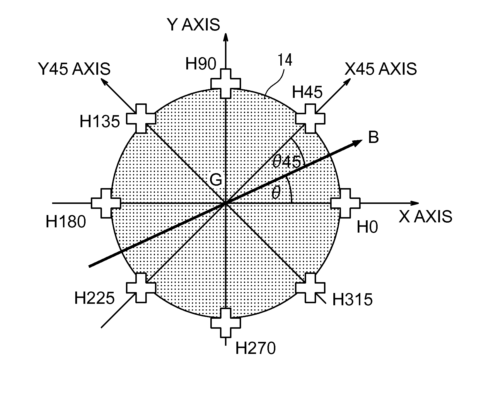
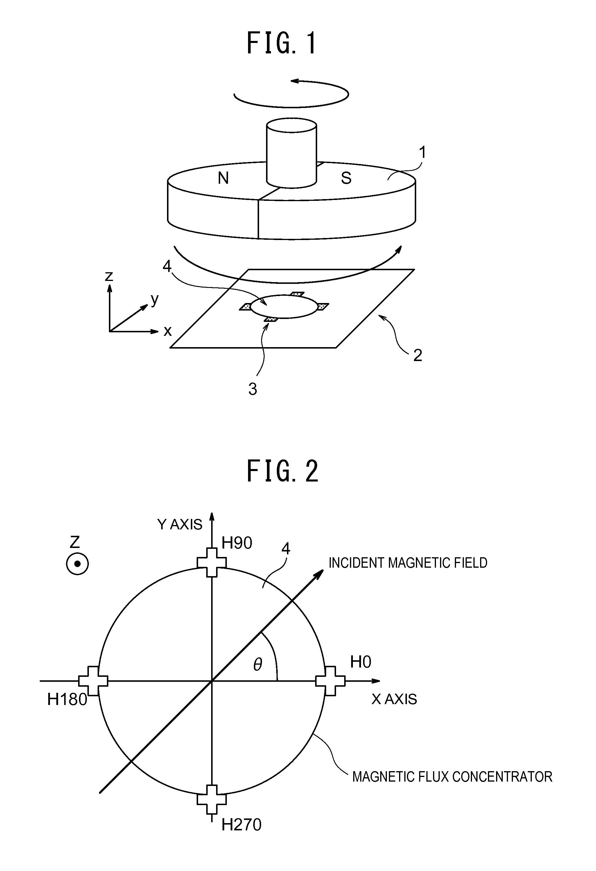
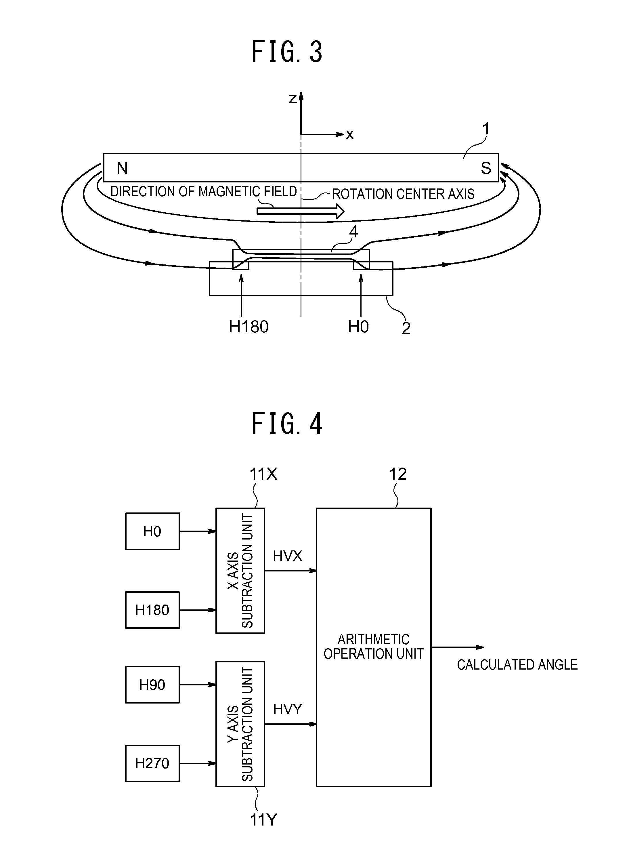
[0079]FIG. 7 is a diagram illustrative of arrangement of Hall elements in a rotation angle measurement apparatus according to the first embodiment of the present invention. Plural Hall elements H0, H45, H90, H135, H180, H225, H270 and H315 are arranged under a circumference of a circular magnetic flux concentrator 14, at intervals of 45 degrees counterclockwise. Among the plural Hall elements H0, H45, H90, H135, H180, H225, H270, and H315, H0 and H180 form a Hall element pair, H45 and H225 form a Hall element pair, H90 and H270 form a Hall element pair, and H135 and H315 form a Hall element pair. The circular magnetic flux concentrator 14 is arranged on magnetosensitive planes of the plural Hall element pairs. In addition, the rotating magnet is arranged in proximity to the magnetic flux concentrator 14 to cover the magnetic flux concentrator 14 in a planar view.

[0080]A center point G of the circular magnetic flux concentrator 14 is also a middle point of the Hall element pair H0 an...

second embodiment

[0130]FIG. 13 is a diagram illustrative of arrangement of Hall elements in a rotation angle measurement apparatus according to the second embodiment of the present invention.

[0131]Twelve Hall elements H0, H30, H60, . . . , H330, in total are arranged under a circumference of a circular magnetic flux concentrator 14, at intervals of 30°. Arrangements of a first Hall element pair 121 (H0 and H180) and a second Hall element pair 122 (H90 and H270) are referred to as arrangement A′. Arrangements of a third Hall element pair 123 (H30 and H210) and a fourth Hall element pair 124 (H120 and H300) are referred to as arrangement B′. Arrangements of a fifth Hall element pair 125 (H60 and H240) and a sixth Hall element pair 126 (H150 and H330) are referred to as arrangement C′.

[0132]In other words, plural Hall element pairs are arranged under the circumference of the magnetic flux concentrator at intervals of 30 degrees.

[0133]The center point G of the circular magnetic flux concentrator is also...

third embodiment

[0170]FIG. 18 is a configuration diagram illustrative of a signal processing circuit of the rotation angle measurement apparatus according to a third embodiment of the present invention. It is to be noted that the arrangements of the magnetic flux concentrator and the Hall elements are same as those in FIG. 7 according to the first embodiment of the present invention.

[0171]The rotation angle measurement apparatus of FIG. 18 includes: the first Hall element pair 21 (H0, H180) in the arrangement A; the second Hall element pair 22 (H90, H270) in the arrangement A; the third Hall element pair 23 (H45, H225) in the arrangement B; the fourth Hall element pair 24 (H135, H315) in the arrangement B; the MUX 25; the X axis subtraction unit 26X; the Y axis subtraction unit 26Y; an angle amplitude calculation unit 40 (including an angle calculation unit 41 and an amplitude calculation unit 42); the first storage register 28a; the second storage register 28b; a third storage register 28c; a four...


PUM


Abstract

A rotation angle measurement apparatus includes: a first Hall element pair for detecting a magnetic component in a first direction; a second Hall element pair for detecting a magnetic component in a second direction different from the first direction; a third Hall element pair for detecting a magnetic component in a third direction different from the first direction and the second direction; and a fourth Hall element pair for detecting a magnetic component in a fourth direction different from the first to third directions. An angle calculation unit calculates a first rotation angle θ of a rotating magnet based upon the strengths of the output signals from the first Hall element pair and the second Hall element pair, and calculates a second rotation angle θc of the rotating magnet based upon the strengths of the output signals from the third Hall element pair and the fourth Hall element pair.

Description

TECHNICAL FIELD[0001]The present invention relates to a rotation angle measurement apparatus using a magnetic flux concentrator.BACKGROUND ART[0002]In recent years, various uses of high-function magnetic sensor LSIs with magnetic detection elements (such as Hall elements or magneto resistance elements) and a signal processing circuit (i.e., LSI) integrated together have been promoted. For example, in automobiles, there is a rotation angle sensor for detecting a rotation angle of a steering wheel. PTL 1, for example, proposes such a rotation angle sensor. PTL 1 discloses a rotation angle sensor using a magnetic flux concentrator for collecting and amplifying surrounding magnetic fields and Hall elements on a silicon substrate.[0003]FIG. 1 is a configuration diagram illustrative of the rotation angle sensor described in PTL 1. The rotation angle sensor includes a rotating magnet 1 attached to a rotor and an integrated circuit (i.e., silicon substrate) 2 disposed under the rotating mag...

Claims


Application Information

Patent Timeline
IPC IPC(8): G01B7/30
CPCG01B7/30G01D5/145G01D5/142G01R33/07
Inventor NAKAMURA, TAKENOBUOKATAKE, SHIGEKI
Owner ASAHI KASEI ELECTRONICS CO LTD
Why Eureka
Try Eureka