
Stun device testing apparatus and methods

Inactive Publication Date: 2014-08-14
AEGIS IND INC
View PDF1 Cites 16 Cited by
  • Summary
  • Abstract
  • Description
  • Claims
  • Application Information

AI Technical Summary

Benefits of technology

The technology described in this patent is about testing devices for stun devices. The testing devices have the ability to measure and record the electrical output of stun devices. They can capture waveform data and analyze it to identify abnormalities or potential safety issues. The testing devices can also record data on the frequency, duration, and repetition rate of the electrical pulses produced by stun devices. The testing devices can be equipped with interchangeable adapters for different stun devices. The technology also includes a housing with a port for receiving the discharge end of an electrical discharge device, and a discharge-receiving circuit with multiple resistors and a default resistor for automatically passing the discharge through. The testing devices can also include an environmental module for detecting temperature, humidity, and pressure, and an air intake fan for drawing ambient air into the housing. The technology also includes a method for configuring the circuit based on the condition of the circuit, such as detecting a loss of power or receiving a new protocol. Overall, the technology provides a detailed and effective way to test stun devices and ensure their safety and performance.

Problems solved by technology

While many are available, however, only a limited number of manufacturers sell stun devices in a gun form-factor.
Manufacturers have conducted various safety studies involving humans and animals to allay public fears and to use as a defense in litigation, where the actual output of the device is considered to have been a cause of injury or death of the target.
Thus, lacking regulatory approval of a universal waveform, each company documents its waveform's safety by performing safety studies for its own devices.
While safety factors of each waveform have been disclosed in publications, the device use data and associated instances of injury and death to date also reveals significant questions regarding safety.
Notwithstanding a manufacturer's claim of safety, electric stun device safety can only be assured if the stated waveform is both proven safe and is consistently produced and delivered by the device.
However, there is no easy, simple way to verify device output on a regular basis within the typical law enforcement context.
While this approach may be helpful in determining the safety of a device right off the assembly line, stun devices are rarely, if ever, tested after being in the field for a period of time.
Moreover, any tests performed on a particular device are often performed only after a discharge against a target has occurred, usually, and unfortunately, after there exists a reason for testing (e.g., an unintentional death of a target during deployment).
These commonly recognized characteristics may not be sufficient, in all circumstances, to determine adequately or reliably the reason for an adverse result (i.e., a death of a target).
Moreover, if one follows the analogy of forensic study of ballistic evidence, it is clear that the capability to collect and analyze electric stun discharge evidence is lacking.
While some attempts are being made to develop systems to test particular stun devices from a specific manufacturer, these attempts do not appear to contemplate a device that test both existing and not-yet-developed stun devices, or to test and compile information on both existing and not-yet-developed stun devices to enable research into the safety and efficacy of electric waveforms and stun devices, generally.
Changes in output can occur due to a number of factors, including, but not limited to, defective manufacture, component failure due to use, current leakage to operator, change in manufacturing components, deliberate alteration of components and power supply, etc.
Thus, manufacturers' stated claims of output should not be relied upon as accurate over the lifetime of use of the device, nor across successor models.
Currently, stun device output is not regulated at the state or federal level with respect to waveform or magnitude, nor are manufacturing standards tied to any stated degree of device performance or acceptable deviation from stated specifications.
Without verification, there is little, if any, accountability for holding manufacturers responsible for quality performance features.
The lack of verification is problematic for law enforcement officials who use the devices routinely and who may be involved in litigation due to a specific, often fatal, incident.
Medical experience has shown that risks from electrical stimulation include abnormal heart rhythms, epileptic seizures, cell injury and death.
For example very fast, high-amplitude transients can produce injury inside of cells.
However, no universal test devices currently exist that can consistently meet the needs described above for known and to-be-developed stun devices.
Additionally, there presently exists no method for imposing accountability on users or manufacturers of stun devices by proving how a particular stun device was operating prior to discharge during routine use against a target.
Moreover, there exists no system for collecting information and storing it reliably for “large data” analysis about stun device discharge characteristics to study the effects of stun devices on an industry-wide basis.

Method used


Image

  • Stun device testing apparatus and methods
  • Stun device testing apparatus and methods
  • Stun device testing apparatus and methods

Examples


example

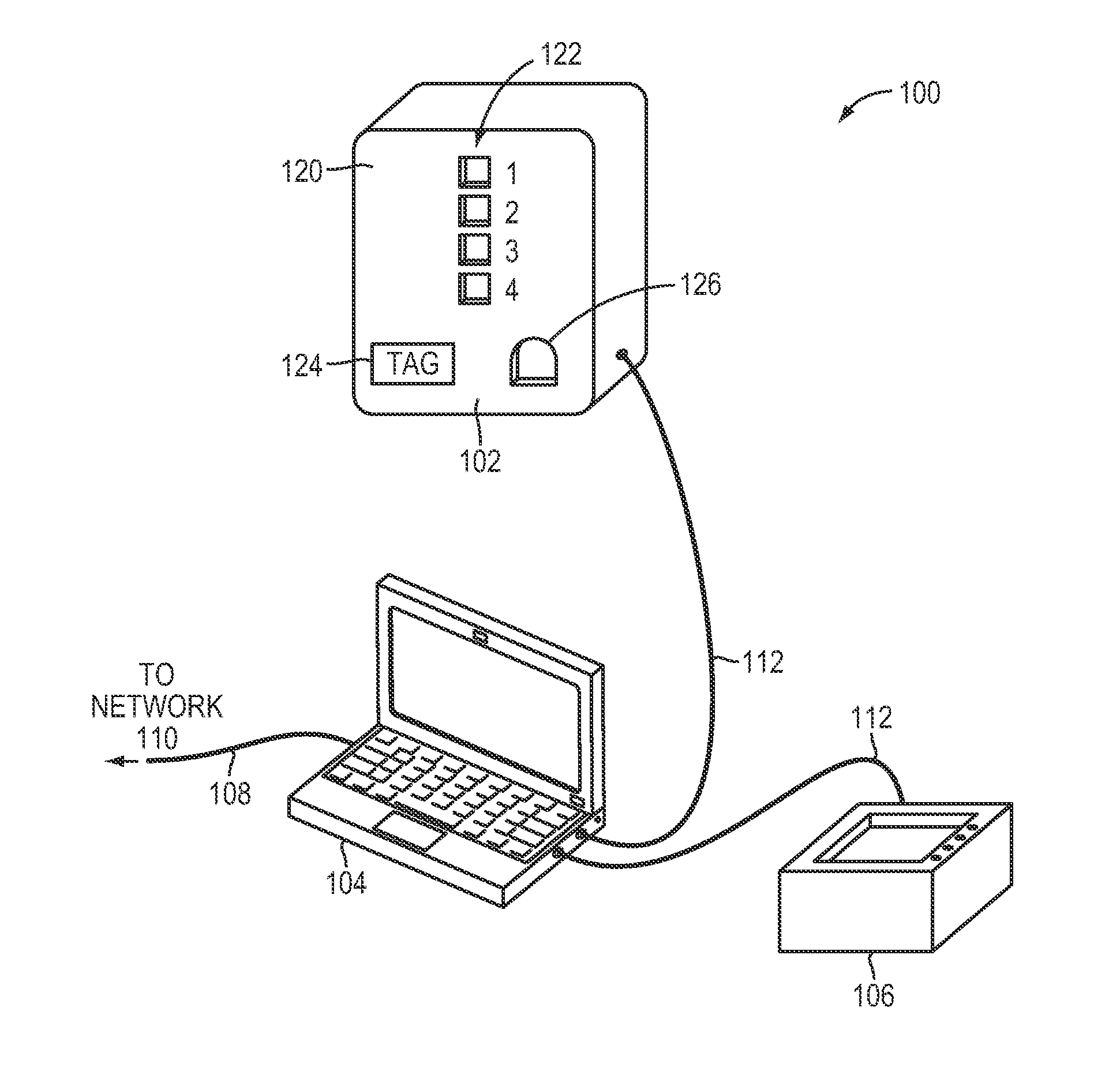
[0091]FIGS. 10-14, as well as FIGS. 15-17D, depict particular construction details of but one example embodiment of a stun device testing system. The figures and associated text are presented as an example only, as other configurations are also contemplated.

[0092]FIG. 10 is a block diagram of a hardware configuration of a stun device testing apparatus 700 in accordance with another embodiment of the technology. The front end board is a printed-circuit assembly that performs the analog data acquisition and control functions for the tester. This board contains a high speed analog-to-digital converter (ADC) configured to measure high voltage pulse waveforms, memory chips to store the acquired waveforms, a complex programmable logic device (CPLD) to manage conversion and transmission of the results to an external processor, environmental sensors, power converters, and a USB 2.0 (Universal Serial Bus) interface chip. The board is used with commercial off-the-shelf (COTS) assemblies to cr...


PUM


Abstract

A testing apparatus includes a housing having a port for receiving a discharge end of an electrical discharge device. A discharge-receiving circuit is operatively connected to the port, and is configured to receive a discharge from the electrical discharge device. The discharge-receiving circuit includes a default resistor and at least one supplemental resistor. When in a first setting, the discharge-receiving circuit is configured so as to pass the discharge automatically through at least the default resistor. When in a second setting, the discharge-receiving circuit is configurable so as to selectively pass the discharge through at least one of the plurality of resistors.

Description

CROSS-REFERENCE TO RELATED APPLICATIONS[0001]This application claims priority to and the benefit of U.S. Provisional Patent Application Ser. No. 61 / 707,101, entitled “Stun Device Testing Apparatus and Methods,” filed Sep. 28, 2012, the disclosure of which is hereby incorporated by reference herein in its entirety.INTRODUCTION[0002]The use of neuromuscular incapacitation (NMI) devices (and other stun devices that emit electrical discharges against a target mammal) has increased over the last decade to encompass over 200,000 units in operation worldwide with over 800,000 actual firing deployments involving training personnel and law enforcement incidents. The output of stun devices is electrical in nature and thus may not leave an identifying mark or clear trace of historical events, unlike a bullet, that normally leaves such a mark. Furthermore, stun devices are designed to incapacitate effectively and temporarily an individual based on a unique and specific electrical output, as sta...

Claims


Application Information

Patent Timeline
IPC IPC(8): F41H13/00G01R27/02
CPCG01R27/02F41H13/0018
Inventor STETHEM, KENNETH J.FRIEDEL, SEYMOURBROMBERG, MICHAEL A.LEWIS, PETERANZELMO, ANTHONY
Owner AEGIS IND INC
Learn More