
Nematic liquid crystal composition and liquid crystal display element using the same

Active Publication Date: 2014-08-14
DAINIPPON INK & CHEM INC
View PDF3 Cites 2 Cited by
  • Summary
  • Abstract
  • Description
  • Claims
  • Application Information

AI Technical Summary

Benefits of technology

The present invention is related to a liquid crystal composition that has several advantages. It has a negative Δ∈, low viscosity, good solubility at low temperatures, and changes in specific resistance and voltage holding ratio due to heat and light are very small. This makes it widely applicable for practical use. The liquid crystal composition can be used for liquid crystal display elements such as VA-type and PSVA-type. It allows for high-speed response and reduces display defects.

Problems solved by technology

However, the stability is not necessarily sufficient.
In particular, liquid crystal compounds having a large Δn have relatively low stability against light and heat, and thus such a composition does not have sufficient quality stability.
However, it has been found that a drop mark formed when a liquid crystal composition is dropped on a substrate results in a problem of a decrease in the display quality.
However, the problem of a drop mark has become a significant problem.
Therefore, in the case where a component having low stability against light is added to the liquid crystal composition, the specific resistance or the voltage holding ratio is decreased, and in some cases, the generation of a drop mark may also be induced, resulting in a problem of a decrease in the yield of the liquid crystal display element due to display defects.

Method used


Image

  • Nematic liquid crystal composition and liquid crystal display element using the same
  • Nematic liquid crystal composition and liquid crystal display element using the same
  • Nematic liquid crystal composition and liquid crystal display element using the same

Examples


example 1

[0077]A liquid crystal composition LC-1 shown below was prepared.

[Chem. 13]Chemical structureRatioAbbreviation24%3-Cy—Cy-210%3-Cy—Cy-4 5%3-Cy—Cy-5 2%3-Cy—Ph—O113%3-Cy—Ph5—O2 9%2-Cy—Ph—Ph5—O2 9%3-Cy—Ph—Ph5—O2 5%3-Cy—Cy—Ph5—O3 6%4-Cy—Cy—Ph5—O2 5%5-Cy—Cy—Ph5—O2 6%3-Ph—Ph5—Ph-2 6%4-Ph—Ph5—Ph-2

[0078]The values of the physical properties of the liquid crystal composition LC-1 were as follows.

TABLE 1TNI / ° C.81.0Δn0.103no1.483ε / / 3.27ε⊥6.18Δε−2.91η / mPa · s20.3γ1 / mPa · s112

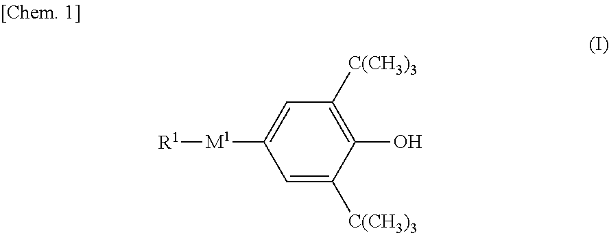
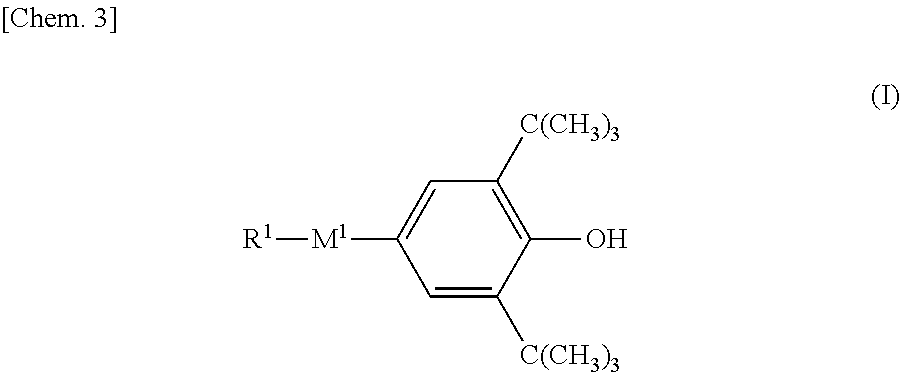
[0079]A liquid crystal composition LCM-1 was prepared by adding 0.03% of a compound represented by formula (I-c-1):

to 99.97% of the liquid crystal composition LC-1. The values of the physical properties of LCM-1 were substantially the same as those of LC-1. The initial VHR of the liquid crystal composition LCM-1 was 98.5%, and the VHR after the composition LCM-1 was left to stand at a high temperature of 150° C. for one hour was 98.5%. A vertical alignment (VA) liquid crystal display element was prepared by using the liquid...

examples 2 to 4

[0088]Liquid crystal compositions LC-3 to LC-5 shown below were prepared, and the values of the physical properties of LC-3 to LC-5 were measured. The results are shown in the table below.

TABLE 6Example 2Example 3Example 4Liquid crystalLiquid crystalLiquid crystalcomposition LC-3composition LC-4composition LC-5TNI / ° C.76.0TNI / ° C.74.9TNI / ° C.76.9Δn0.103Δn0.102Δn0.117no1.484no1.484no1.489ε / / 3.34ε / / 3.23ε / / 3.20ε⊥6.25ε⊥6.09ε⊥6.22Δε−2.91Δε−2.86Δε−3.02η / mPa · s19.8η / mPa · s21.1η / mPa · s20.5γ1 / mPa · s110γ1 / mPa · s116γ1 / mPa · s1163-Cy-Cy-224% 3-Cy-Cy-222% 5-Ph-Ph-113% 3-Cy-Cy-410% 3-Cy-Cy-411% 3-Cy-Cy-V18% 3-Cy-Ph-O17%5-Ph-Ph-18%3-Cy-Cy-V17%3-Cy-Ph5-O214% 3-Cy-Cy-Ph-12%V-Cy-Cy-Ph-15%2-Cy-Ph-Ph5-O27%3-Cy-Ph5-O27%3-Cy-Ph5-O27%3-Cy-Ph-Ph5-O29%3-Cy-Ph5-O48%3-Cy-Ph5-O48%3-Cy-Cy-Ph5-O35%2-Cy-Ph-Ph5-O26%2-Cy-Ph-Ph5-O26%4-Cy-Cy-Ph5-O27%3-Cy-Ph-Ph5-O27%3-Cy-Ph-Ph5-O27%5-Cy-Cy-Ph5-O25%3-Cy-Cy-Ph5-O37%3-Cy-Cy-Ph5-O37%3-Ph-Ph5-Ph-26%4-Cy-Cy-Ph5-O27%4-Cy-Cy-Ph5-O27%4-Ph-Ph5-Ph-26%5-Cy-Cy-Ph5-O27%5-Cy-Cy...

examples 5 to 7

[0091]Liquid crystal compositions LC-6 to LC-8 shown below were prepared, and the values of the physical properties of LC-6 to LC-8 were measured. The results are shown in the table below.

TABLE 8Example 5Example 6Example 7Liquid crystalLiquid crystalLiquid crystalcomposition LC-6composition LC-7composition LC-8TNI / ° C.80.1TNI / ° C.80.4TNI / ° C.80.2Δn0.093Δn0.113Δn0.1119no1.479no1.487no1.4850ε / / 3.14ε / / 3.19ε / / 3.30ε⊥6.09ε⊥6.18ε⊥6.24Δε−2.95Δε−2.99Δε−2.94η / mPa · s19.0η / mPa · s20.2η / mPa · s18.7γ1 / mPa · s96γ1 / mPa · s107γ1 / mPa · s1083-Cy-Cy-223% 5-Ph-Ph-110% 3CyPhO14%3-Cy-Cy-46%3-Cy-Cy-V20% 3-Cy-Cy-V25% 3-Cy-Cy-V9%3-Cy-Cy-V19%3-Cy-Cy-V110% 3-Cy-Cy-V15%V-Cy-Cy-Ph-14%2-Cy-Ph5-O27%3-Cy-Ph5-O27%3-Cy-Ph5-O27%3-Cy-Ph5-O48%3-Cy-Ph5-O47%3-Cy-Ph5-O47%2-Cy-Ph-Ph5-O25%2-Cy-Ph-Ph5-O26%2-Cy-Ph-Ph5-O26%3-Cy-Ph-Ph5-O26%3-Cy-P-hPh5-O27%3-Cy-Ph-Ph5-O27%3-Cy-Cy-Ph5-O36%3-Cy-Cy-Ph5-O37%3-Cy-Cy-Ph5-O37%4-Cy-Cy-Ph5-O27%4-Cy-Cy-Ph5-O28%4-Cy-Cy-Ph5-O28%5-Cy-Cy-Ph5-O26%5-Cy-Cy-Ph5-O27%5-Cy-Cy-Ph5-O27%3-Ph-Ph5-Ph-28%...


PUM


Abstract

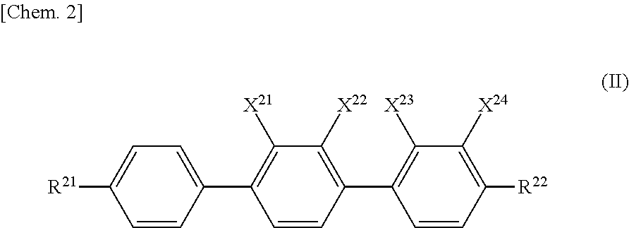
The nematic liquid crystal composition exhibits a negative dielectric anisotropy (Δ∈), the liquid crystal composition being useful as a liquid crystal display material, and a liquid crystal display element using the same. The liquid crystal composition of the present invention has a large absolute value of the dielectric anisotropy thereof and a low viscosity. By using this liquid crystal composition, it is possible to provide a liquid crystal display element which has a high contrast, high-speed responsiveness, and good display quality in which image sticking and display defects are not generated. The liquid crystal display element using the liquid crystal composition is a useful display element which realizes both high-speed response and suppression of display defects. In particular, the liquid crystal display element is useful as a liquid crystal display element for active-matrix driving, and can be applied to, for example, a VA-type or PSVA-type liquid crystal display element.

Description

TECHNICAL FIELD[0001]The present invention relates to a nematic liquid crystal composition that exhibits a negative dielectric anisotropy (Δ∈), the liquid crystal composition being useful as a liquid crystal display material, and a liquid crystal display element using the same.BACKGROUND ART[0002]Liquid crystal display elements are used in not only watches and electronic calculators, but also various measuring instruments, panels for automobiles, word processors, electronic notebooks, printers, computers, televisions, clocks, advertisement display boards, etc. Typical examples of a liquid crystal display system include a twisted nematic (TN)-type display, a super-twisted nematic (STN)-type display, a vertical alignment (VA)-type display using a thin-film transistor (TFT), and an in-plane-switching (IPS)-type display. It is desired that liquid crystal compositions used in these liquid crystal display elements be stable against external factors such as moisture, air, heat, and light, ...

Claims


Application Information

Patent Timeline
IPC IPC(8): C09K19/30C09K19/56G02F1/133
CPCC09K19/3003G02F1/133C09K19/56C09K2019/3016C09K2019/3009C09K2019/301C09K2019/3004C09K19/062C09K19/44C09K2019/0448C09K2019/122C09K2019/123C09K2323/00C09K19/42C09K19/46G02F1/13
Inventor KURIYAMA, TAKESHIIWASHITA, YOSHINORI
Owner DAINIPPON INK & CHEM INC
Learn More