

Method and apparatus for cleaning photomask handling surfaces
- Summary
- Abstract
- Description
- Claims
- Application Information
AI Technical Summary
Benefits of technology
Problems solved by technology
Method used
Image

Examples
Embodiment Construction
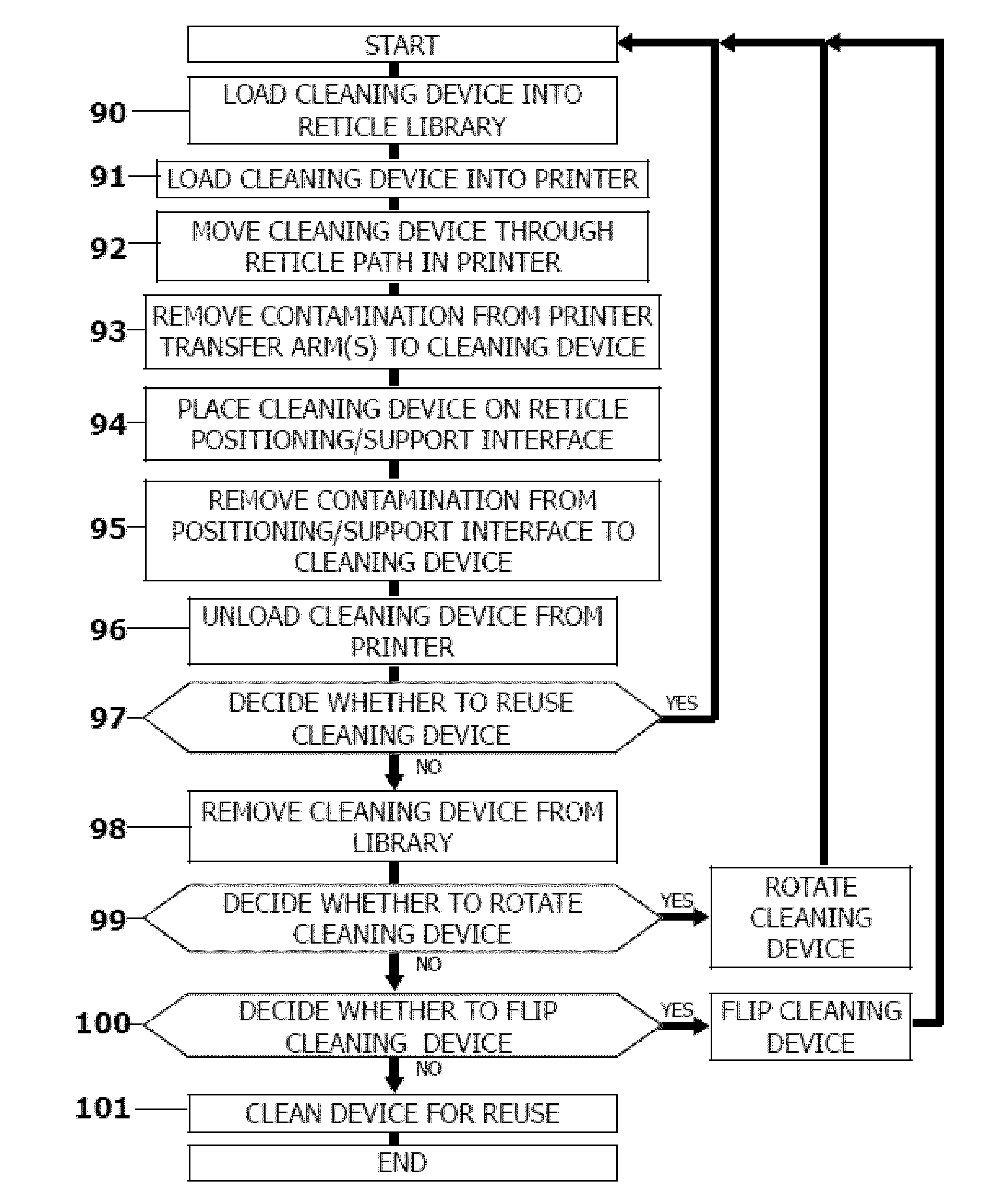
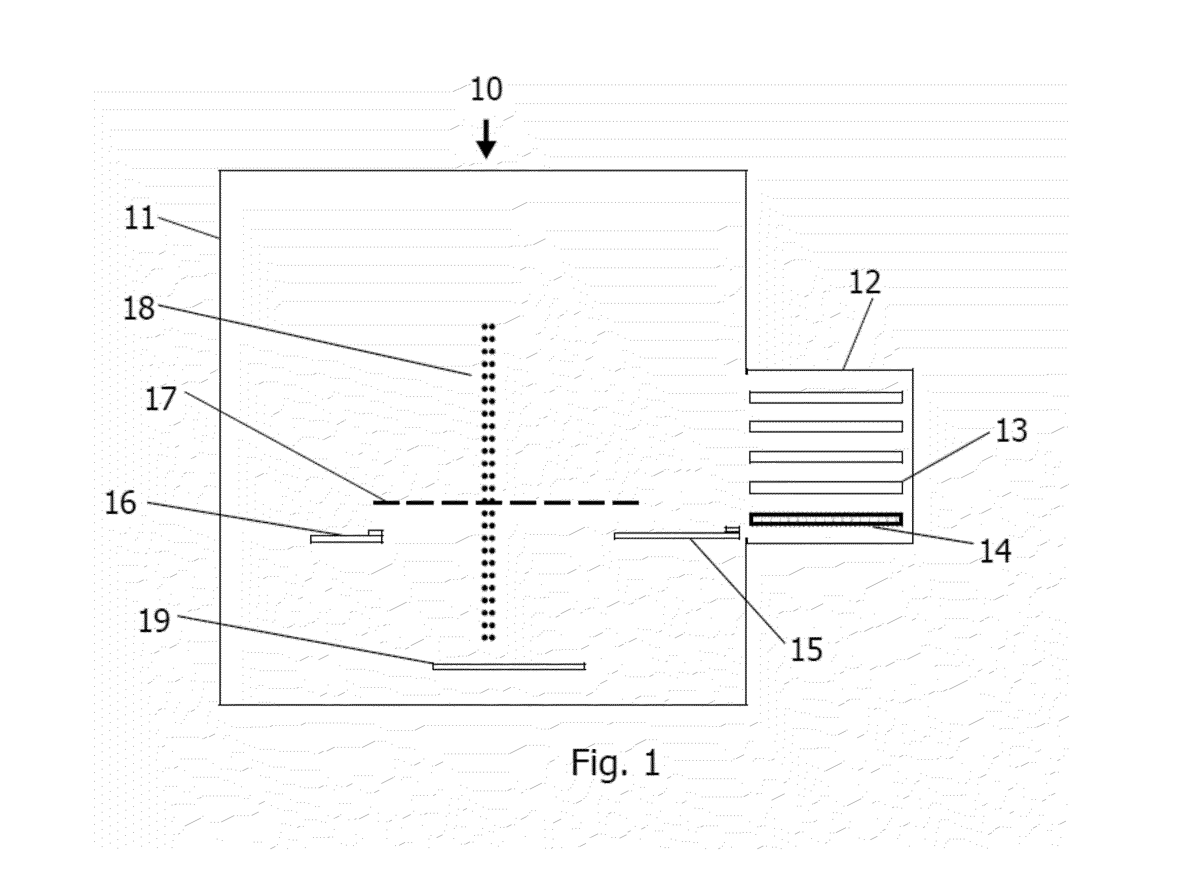
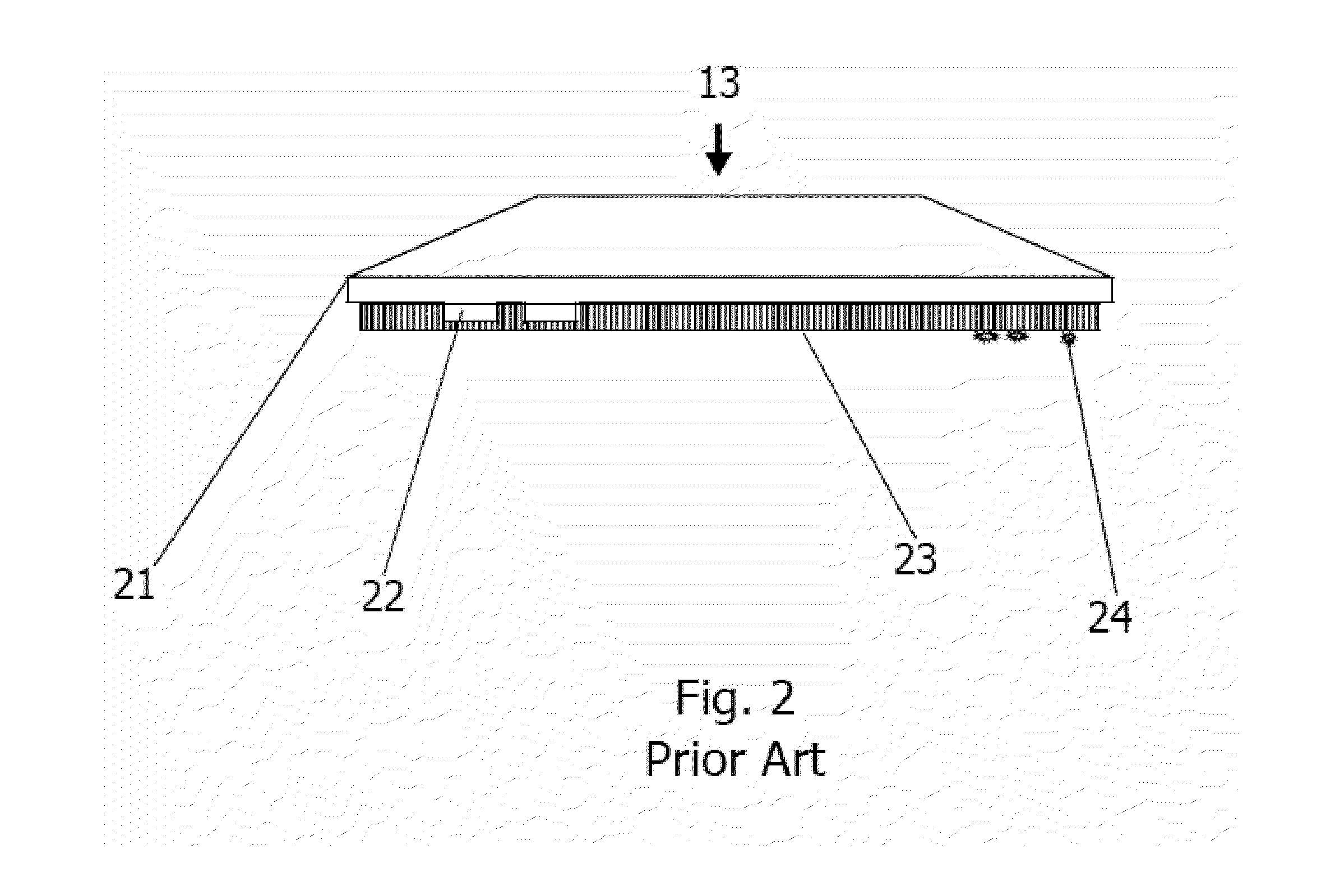
[0019]Integrated circuit manufacturing may benefit by providing a quick and simple method for automatically cleaning the robot transfer arm(s) and the reticle positioning / support interface of reticle transfer and placement equipment in order to remove contamination and particulates which may migrate from the transfer and support components onto the area of the reticle containing the circuit pattern where it may block incident light from replicating the designed pattern features, resulting in non-functional electrical circuits. Similarly, integrated circuit manufacturing may also benefit by providing an automatic method for cleaning reticle transfer and positioning / support components in order to remove contamination and particulates that may cause the reticle to be lifted up at one or more edges into a position not perpendicular to the incident beam in the printer, a condition that also produces non-functional electrical circuits. In addition, since the reticle is typically stepped o...
PUM
 Abstract
Description
Claims
Application Information