Multi-mode optical measurement device and method of operation

a multi-mode optical measurement and optical measurement technology, applied in the field of optical measurement devices, can solve the problems of electronic noise and atmospheric turbulence that may be much greater

Active Publication Date: 2014-08-14
FARO TECH INC
View PDF2 Cites 53 Cited by
  • Summary
  • Abstract
  • Description
  • Claims
  • Application Information

AI Technical Summary

Problems solved by technology

Thus, laser scanners can operate at higher laser power levels and operate with non-cooperating targets, albeit typically at lower accuracy an

Method used


Image

  • Multi-mode optical measurement device and method of operation
  • Multi-mode optical measurement device and method of operation
  • Multi-mode optical measurement device and method of operation

Examples


Embodiment Construction

[0028]Embodiments of the present invention provide for an optical measurement device that may operate as either a laser tracker or a laser scanner. This provides advantages in allowing either a higher accuracy measurement using a cooperative target, usually handheld by an operator, or a faster (usually) lower accuracy measurement, usually without the active assistance of an operator. These two modes of operation are provided in a single integrated device.

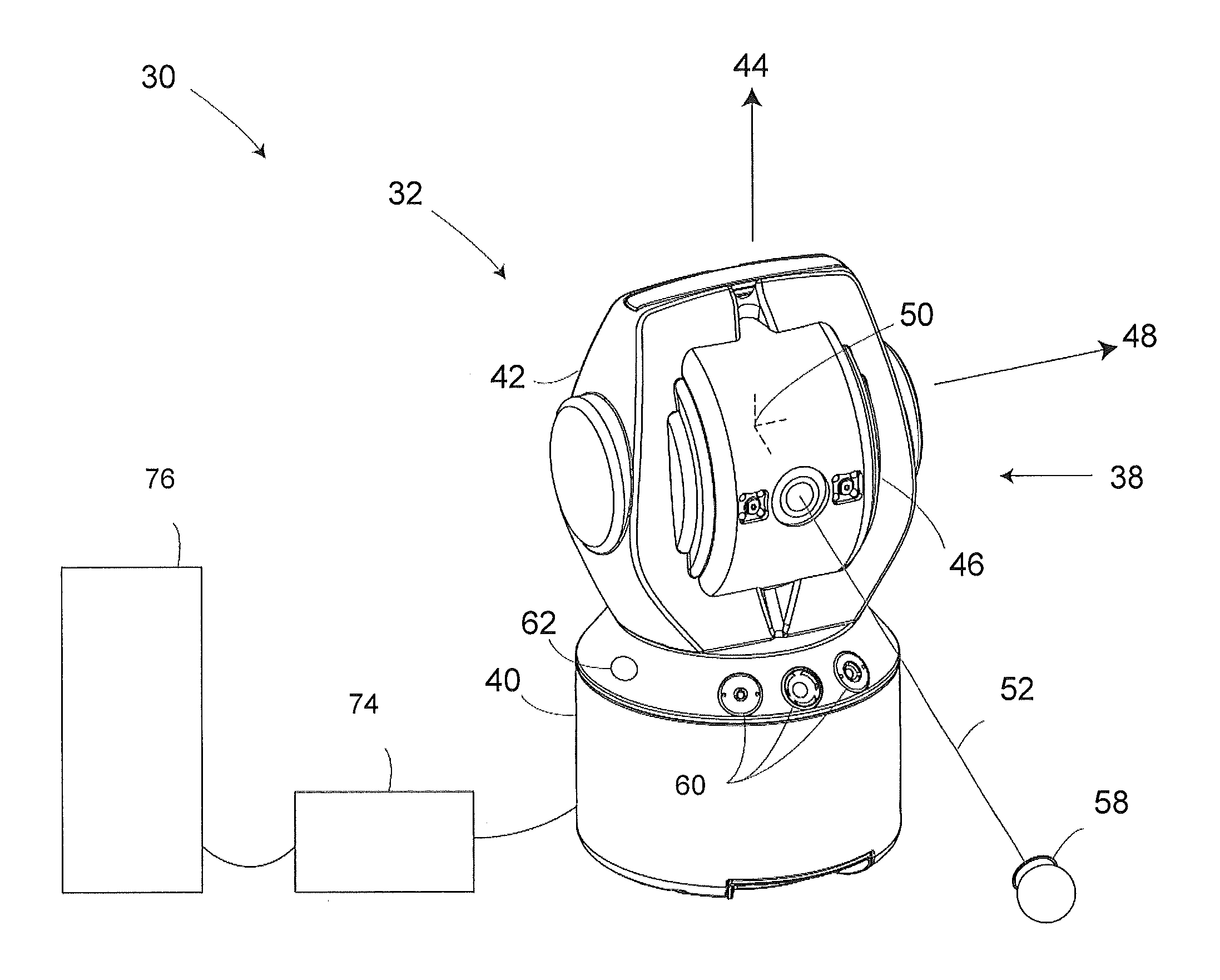
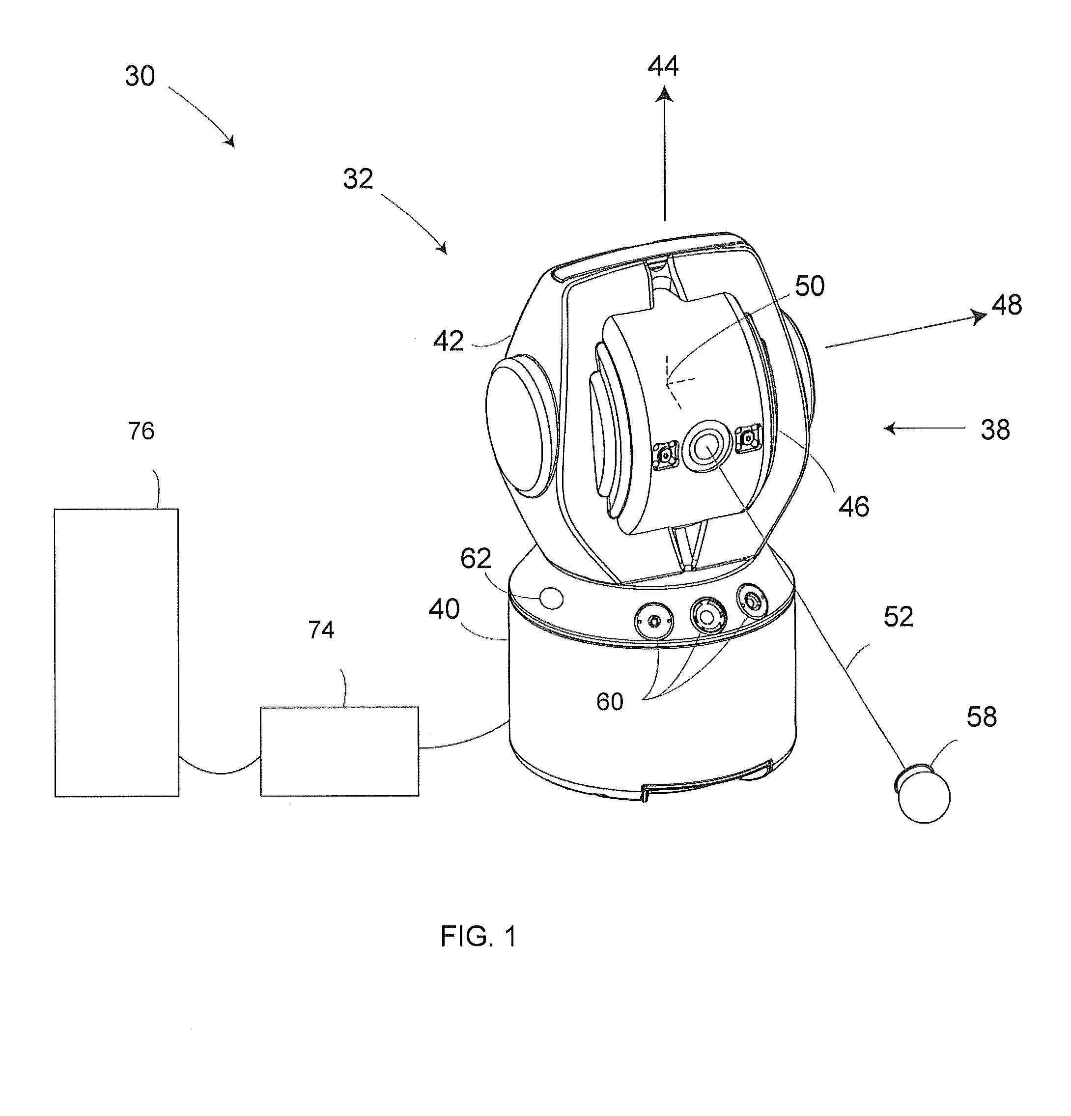
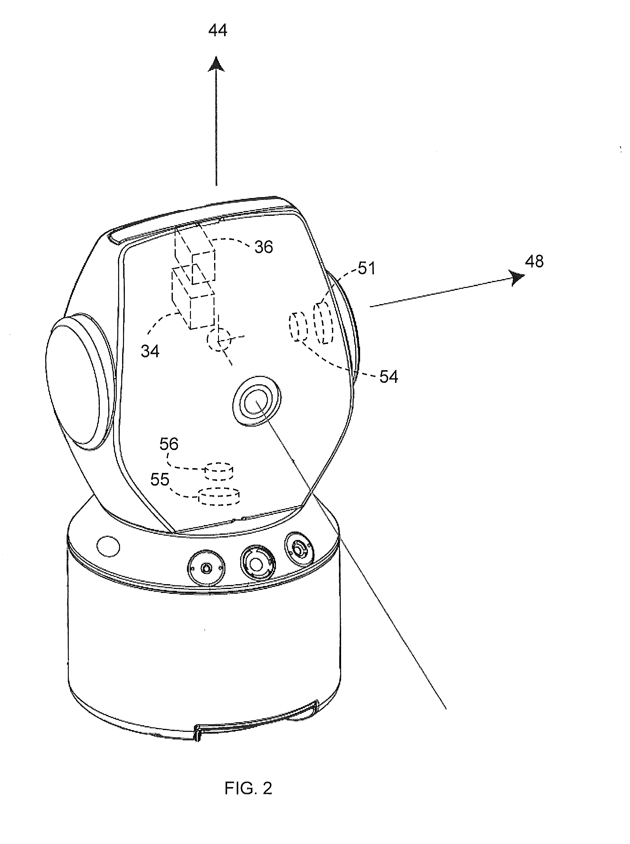
[0029]Referring now to FIGS. 1-2, an optical measurement device 30 is shown that provides for multiple modes of operation. The device 30 has a housing 32 containing tracker portion 34 to support laser tracking functionality and a scanner portion 36 to support scanner functionality. An exemplary gimbaled beam steering mechanism 38 includes a zenith carriage 42 mounted on an azimuth base 40 and rotated about an azimuth axis 44. A payload structure 46 is mounted on the zenith carriage 42, which rotates about a zenith axis 48. The zenit...


PUM


Abstract

An optical measurement device is provided includes a tracker device configured to emit a first beam of light and receive a portion of the first beam of light reflected off of a target. The first beam of light being emitted from a gimbal location, the tracker device further including an absolute distance meter configured to determine the distance to the target. A scanner device is provided that is configured to emit a second beam of light along a pathway without reversing direction and receive a portion of the second beam of light reflected off an object. The second beam of light being emitted from the gimbal location, the scanner further being configured to determine the distance to the object based at least in part on the speed of light.

Description

BACKGROUND OF THE INVENTION[0001]The subject matter disclosed herein relates to an optical measurement device that measures dimensional coordinates, and in particular to a noncontact optical measurement device have multiple optical devices for measuring an object.[0002]Noncontact optical measurement devices may be used to determine the coordinates of points on an object. One type of optical measurement device measures the three-dimensional (3D) coordinates of a point by sending a laser beam to the point. The laser beam may impinge directly on the point or on a retroreflector target in contact with the point. In either case, the instrument determines the coordinates of the point by measuring the distance and the two angles to the target. The distance is measured with a distance-measuring device such as an absolute distance meter or an interferometer. The angles are measured with an angle-measuring device such as an angular encoder. A gimbaled beam-steering mechanism within the instru...

Claims


Application Information

Patent Timeline
IPC IPC(8): G01B11/00G01S17/89
CPCG01B11/002G01C15/002G01S17/66G01S17/89G01S7/4808G01S7/4813G01S7/4818G01S7/4817
Inventor STEFFEY, KENNETHBRIDGES, ROBERT E.PARKER, DAVID H.
Owner FARO TECH INC
Why Eureka
Try Eureka