Hearing aid antenna

a technology for hearing aids and antennas, applied in the direction of resonant antennas, antenna equipments with additional functions, sets using external connections, etc., can solve the problems of inability to establish communication, antennas that require a lot of design effort each time, etc., and achieve the effect of maximizing path gain and significantly reducing penetration through the body

Active Publication Date: 2014-08-14
NXP BV
View PDF17 Cites 18 Cited by
  • Summary
  • Abstract
  • Description
  • Claims
  • Application Information

AI Technical Summary

Benefits of technology

[0056]At UHF and higher frequencies like 2.5 GHz, penetration through the body may be significantly reduced and the main mechanism for propagation around the body may be via a creeping wave that follows the dielectric-air interface at the body surface. Such propagation may be initiated by an on-body antenna which directs maximum radiation tangential to the body surface, minimizing off-body radiation, maximizing path gain between body-worn devices. For on-body systems, where both the transmitting and receiving antennas are positioned close to the body surface, there are a number of wave propagation mechanisms: the direct (space) wave, reflected waves, surface waves and diffracted creeping waves.

Problems solved by technology

This antenna occupies large areas of the hearing aid and is not able to establish communication between two hearing aids, each positioned at one ear.
However th

Method used


Image

  • Hearing aid antenna
  • Hearing aid antenna
  • Hearing aid antenna

Examples


Embodiment Construction

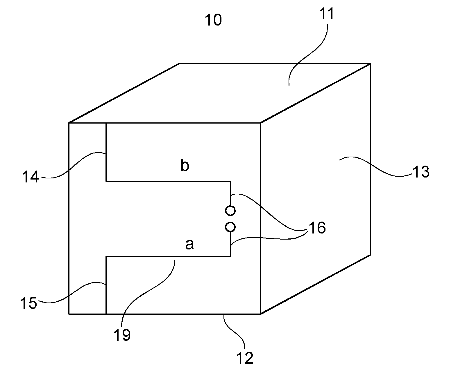
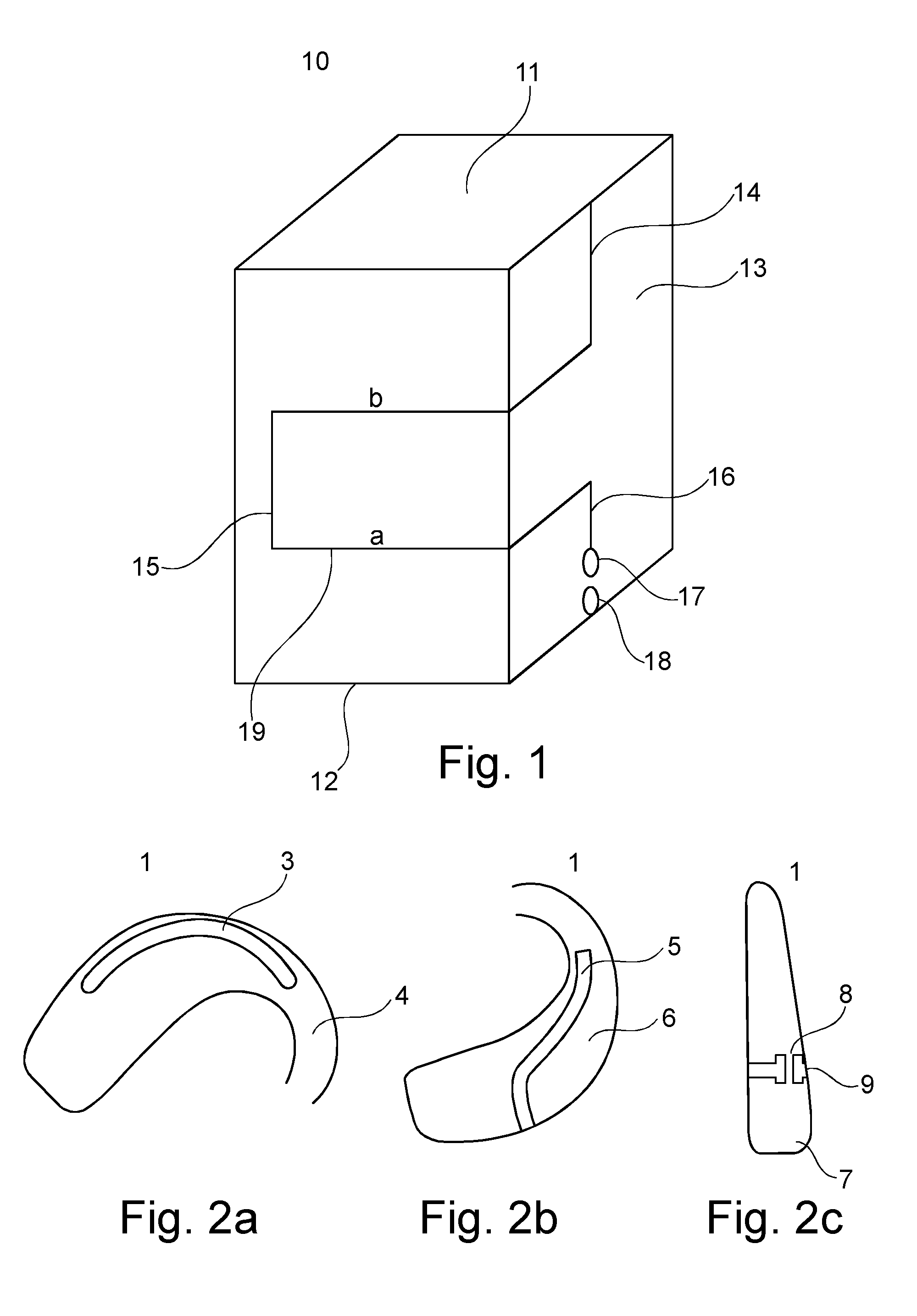
[0079]The illustration in the drawing is schematical. In different drawings, similar or identical elements are provided with the same reference signs.

[0080]FIG. 2a illustrates a conventional antenna 1′ in a hearing aid used for electromagnetic on-body communication.

[0081]Integrating an antenna 1′ that suits electromagnetic radiation in a hearing aid faces different problems. A hearing aid has usually a dedicated design and is has a small volume. There is very little volume left for the antenna. It is well known in the art that the antenna volume defines the antenna parameters. Size of an antenna can be expressed as “ka” where k is the free space wave number 2π / λ, where λ is the free space wavelength, and “a” is the radius of an imaginary sphere circumscribing the maximum dimension of the antenna. A value of ka<0.5 is considered as electrically small antenna.

[0082]FIG. 2a, b, c each illustrate the same conventional antenna 1 in a hearing aid used for electromagnetic on-body communica...


PUM

PropertyMeasurementUnit
Electrical conductivityaaaaaaaaaa
Magnetic fieldaaaaaaaaaa
Electrical inductanceaaaaaaaaaa

Abstract

An antenna, in particular a dipole antenna, for radio communication in a hearing aid, is disclosed. The antenna includes a solid three-dimensional dielectric support body, an electrically conductive first plate on a first surface of the support body and an electrically conductive second plate on a second surface of the support body. The first surface and the second surface are arranged on opposing ends of the support body. An electrically conductive filament is arranged on and/or in the support body, electrically coupling the first plate with the second plate, and comprising first sections and second sections. The second sections extend perpendicular to the first sections.

Description

FIELD OF THE INVENTION[0001]The present invention is related to an antenna for communication systems and hearing aids as well as corresponding manufacturing methods. The present invention is directed to the use of a hearing aid or multiple hearing aids as wireless communication devices and in particular to communicate data and in particular high quality audio communication. High quality audio can be understood like CD like quality sound with larger bandwidth than voice audio.BACKGROUND OF THE INVENTION[0002]A basic hearing aid comprises a microphone, speaker and audio transceiver. In such hearing aids the earpiece microphone converts acoustic waves into electrical signals representing the acoustical waves, the electrical signals are amplified and eventual processed and converted back into acoustical waves.[0003]Remote controls with functions to control the amplification and other settings of the earpiece are often used and offer possibly wireless communicating with the earpiece. Som...

Claims


Application Information

Patent Timeline
IPC IPC(8): H04R25/00H01Q9/16
CPCH04R25/552H01Q9/16H01Q1/273H01Q1/44H01Q9/285H04R25/55H04R2225/51H04R25/609Y10T29/49016
Inventor KERSELAERS, ANTHONY
Owner NXP BV
Why Eureka
Try Eureka