
Fuel injection control system for an internal combustion engine

a control system and internal combustion engine technology, applied in the direction of electric control, liquid fuel feeders, machines/engines, etc., can solve the problems of fuel vapor generation fear, inability to determine, and feed pressure cannot be made smaller according to the size of the feed pressure, so as to suppress the generation of vapor

Inactive Publication Date: 2014-08-21
TOYOTA JIDOSHA KK
View PDF1 Cites 9 Cited by
  • Summary
  • Abstract
  • Description
  • Claims
  • Application Information

AI Technical Summary

Benefits of technology

The patent invention relates to a fuel injection control system for an internal combustion engine that has both a low pressure fuel pump and a high pressure fuel pump. The system can achieve low feed pressure while minimizing the formation of vapor. Basically, the system prevents wasted fuel from being injected into the engine, reducing fuel consumption and vapor production.

Problems solved by technology

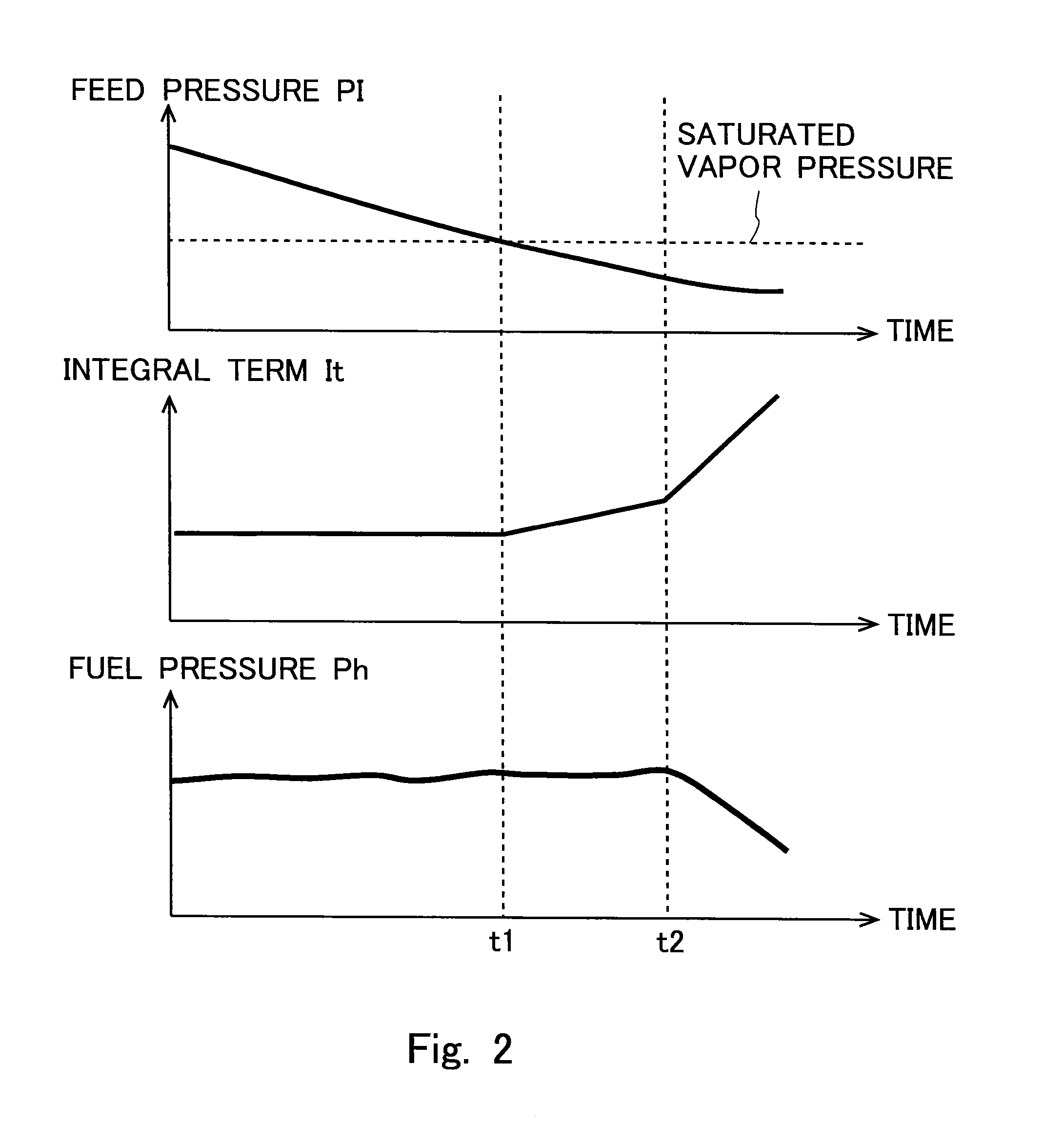
However, when the feed pressure becomes lower than a saturated vapor pressure of fuel, there will be a fear that fuel vapor may be generated.
Accordingly, it becomes impossible to determine, based on the driving duty of the high pressure fuel pump, whether vapor has been generated or not.
However, when the high pressure fuel pump is in a stopped state, the integral term cannot be obtained, so the feed pressure cannot be made smaller according to the rate of change of the integral term.

Method used


Image

  • Fuel injection control system for an internal combustion engine
  • Fuel injection control system for an internal combustion engine
  • Fuel injection control system for an internal combustion engine

Examples


first embodiment

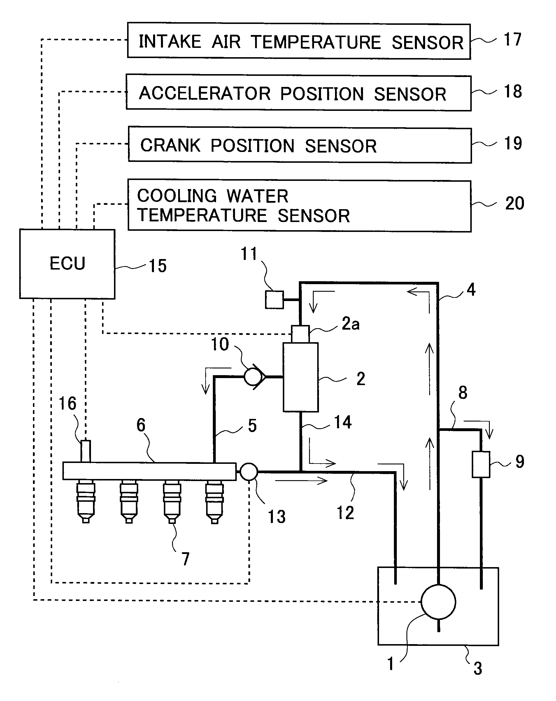
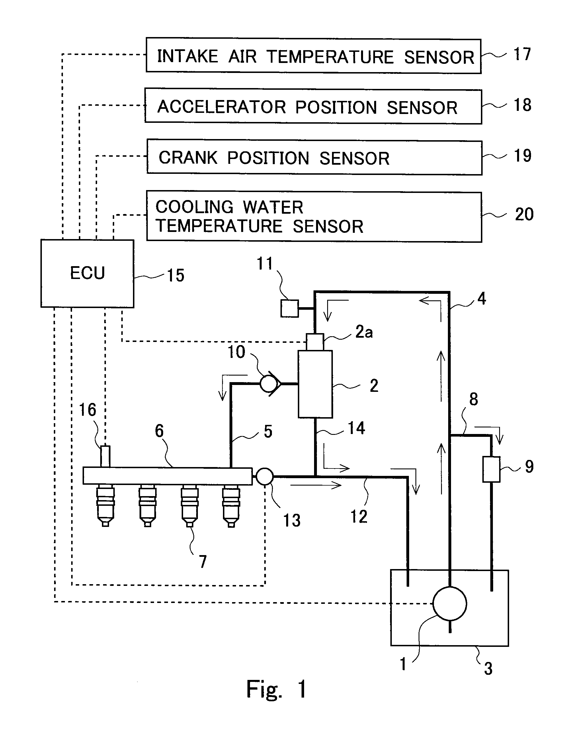
[0043]FIG. 1 is a view showing the schematic construction of a fuel injection control system for an internal combustion engine. The fuel injection control system shown in FIG. 1 is one applied to an internal combustion engine having in-line four cylinders, and is provided with a low pressure fuel pump 1 and a high pressure fuel pump 2. Here, note that the number of cylinders of the internal combustion engine is not limited to four, but may be five or more, or may be three or less.

[0044]The low pressure fuel pump 1 is a pump for pumping or drawing up fuel stored in a fuel tank 3, and is a turbine type pump (WESCO type pump) which is driven by electric power. The fuel delivered from the low pressure fuel pump 1 is led to a suction port of the high pressure fuel pump 2 through a low pressure fuel passage 4.

[0045]The low pressure fuel pump 1 is a pump for pressurizing the fuel delivered from the low pressure fuel pump 1, and is a reciprocating type pump (plunger type pump) which is driv...


PUM


Abstract

In a fuel injection control system for an internal combustion engine provided with a low pressure fuel pump and a high pressure fuel pump, proportional plus integral control of a high pressure fuel pump is carried out to make a pressure of fuel come close to a target value between the high pressure fuel pump and fuel injection valves. In cases where the high pressure fuel pump is in operation, a feed pressure, which is a pressure of fuel between a low pressure fuel pump and the high pressure fuel pump, is caused to go down when an integral term in the proportional plus integral control does not change or is decreasing, and the feed pressure is caused to go up when the integral term is increasing. In cases where the high pressure fuel pump is in a stopped state, the feed pressure is made higher than before the high pressure fuel pump is stopped.

Description

TECHNICAL FIELD[0001]The present invention relates to a fuel injection control system for an internal combustion engine.BACKGROUND ART[0002]In fuel injection control systems for internal combustion engines in which fuel is directly injected into each cylinder, there has been known one which is provided with a low pressure fuel pump that serves to draw up fuel from a fuel tank, and a high pressure fuel pump that serves to cause the fuel thus drawn up by the low pressure fuel pump to rise up to a pressure at which the fuel can be injected into each cylinder.[0003]In the fuel injection control systems as mentioned above, in order to suppress the energy consumption accompanying the operation of the low pressure fuel pump, it is desired to decrease a pressure (also called a feed pressure) at the downstream side of the low pressure fuel pump as much as possible. However, when the feed pressure becomes lower than a saturated vapor pressure of fuel, there will be a fear that fuel vapor may ...

Claims


Application Information

Patent Timeline
IPC IPC(8): F02M69/02
CPCF02M69/02F02D41/123F02D41/1401F02D41/3082F02D41/3845F02D41/3854F02D41/3863F02D2041/1409F02D2200/021F02D2200/0414F02D2250/02F02D2250/31
Inventor KOJIMA, SUSUMUSUGIMOTO, TOMOJIRO
Owner TOYOTA JIDOSHA KK
Learn More