Fluid monitoring and control system

a technology of fluid monitoring and control system, applied in the direction of valve operating means/release devices, process and machine control, instruments, etc., can solve the problems of aging product lines and sagging margins, no practical solution for detection of very small leakage in the plumbing system, and created enormous untapped opportunities. , to achieve the effect of better controlling the use of fluid

Active Publication Date: 2014-08-21
FORTUNE BRANDS WATER INNOVATIONS LLC
View PDF1 Cites 60 Cited by
  • Summary
  • Abstract
  • Description
  • Claims
  • Application Information

AI Technical Summary

Benefits of technology

[0019]In other exemplary embodiments it may include providing a proximity sensor in communication with the central processor of the central hub. Furthermore, this may include providing a second temperature threshold, a second pressure threshold or a second flow rate threshold utilized for monitoring by the software, and including the step of the user commanding the software to utilize the second thresholds through the user interface or the step of the software automatically utilizing the second thresholds based upon an input from the proximity sensor. In this way a vacation mode can be entered where a burglar use or other unexpected fluid flow use may be quickly determined and the control device closed and an alert message sent to the user. Also, in this way use of the fluid can be better controlled based upon the movements of the user within a building or structure.

Problems solved by technology

The net effect of this stagnation has become aging product lines and sagging margins.
Emergence of environmental, health, safety, conservation and also the increasing need for water damage mitigation has created enormous untapped opportunities.
Furthermore, there are no practical solutions for detection of very small leaks in the plumbing systems.
These leaks cause hundreds of millions of dollars in mold and property damage in United States alone.

Method used


Image

  • Fluid monitoring and control system
  • Fluid monitoring and control system
  • Fluid monitoring and control system

Examples


Embodiment Construction

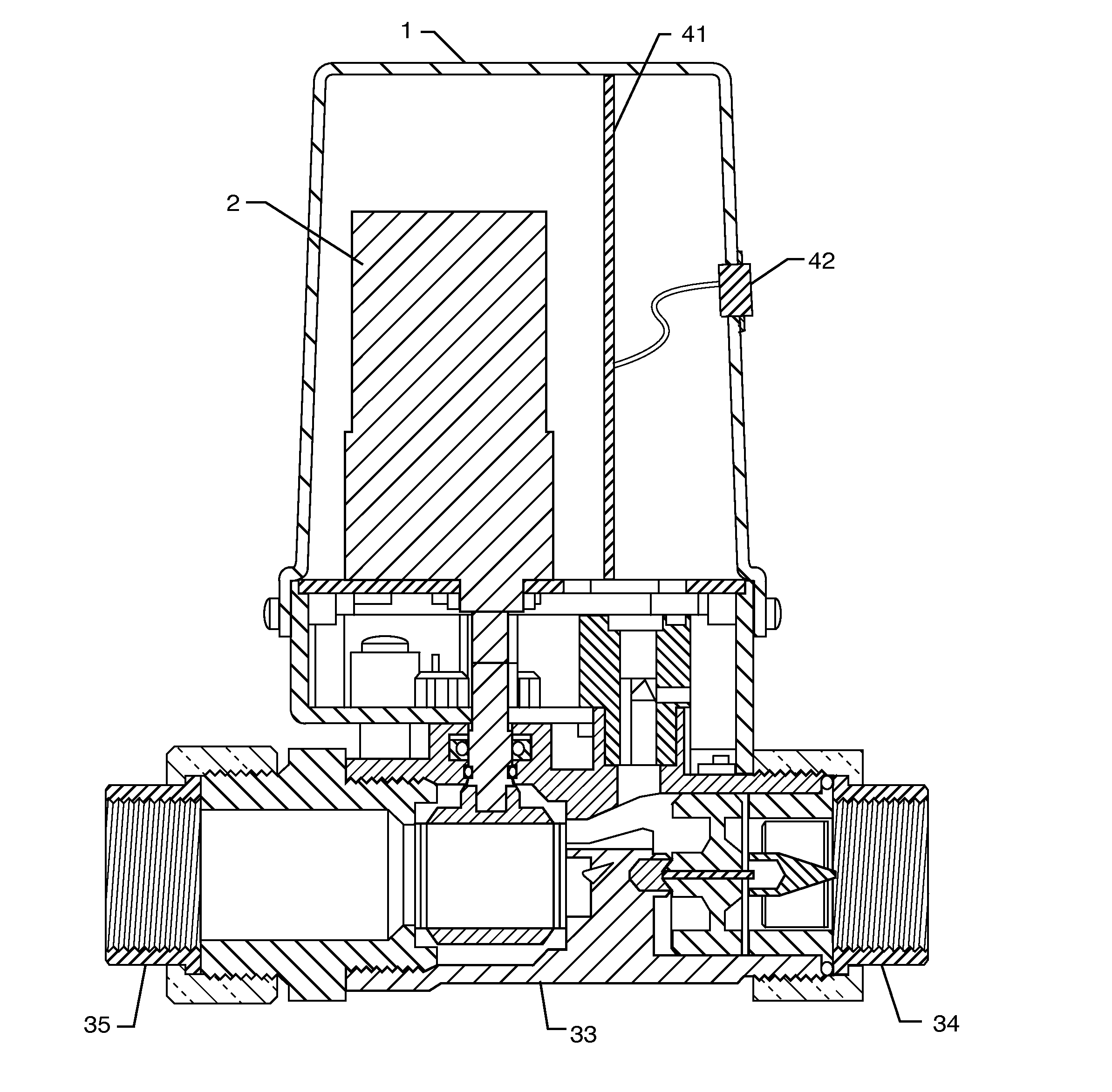
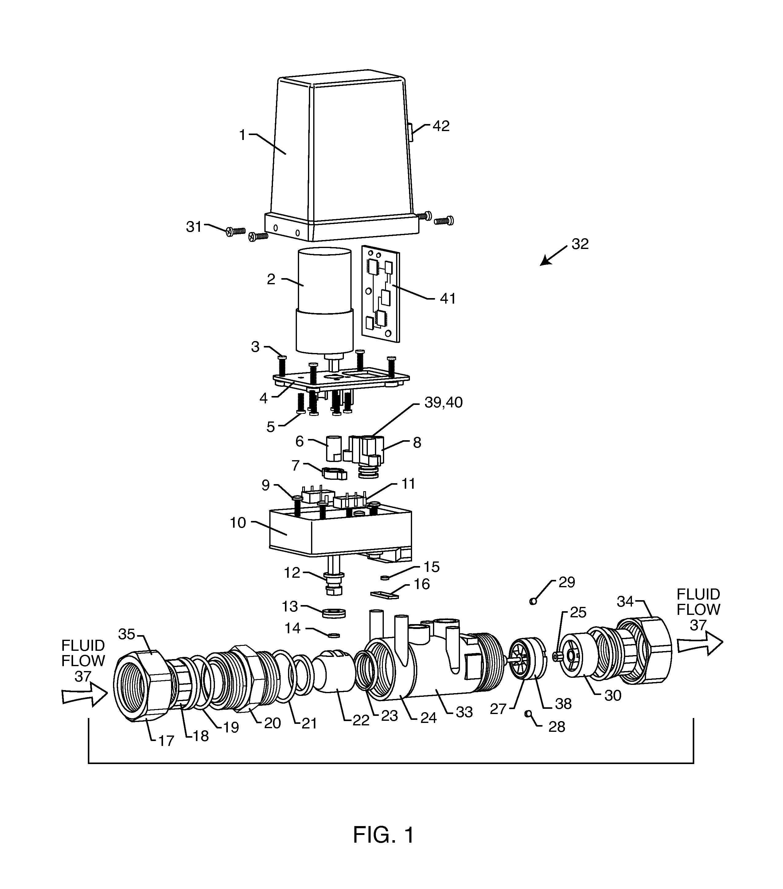
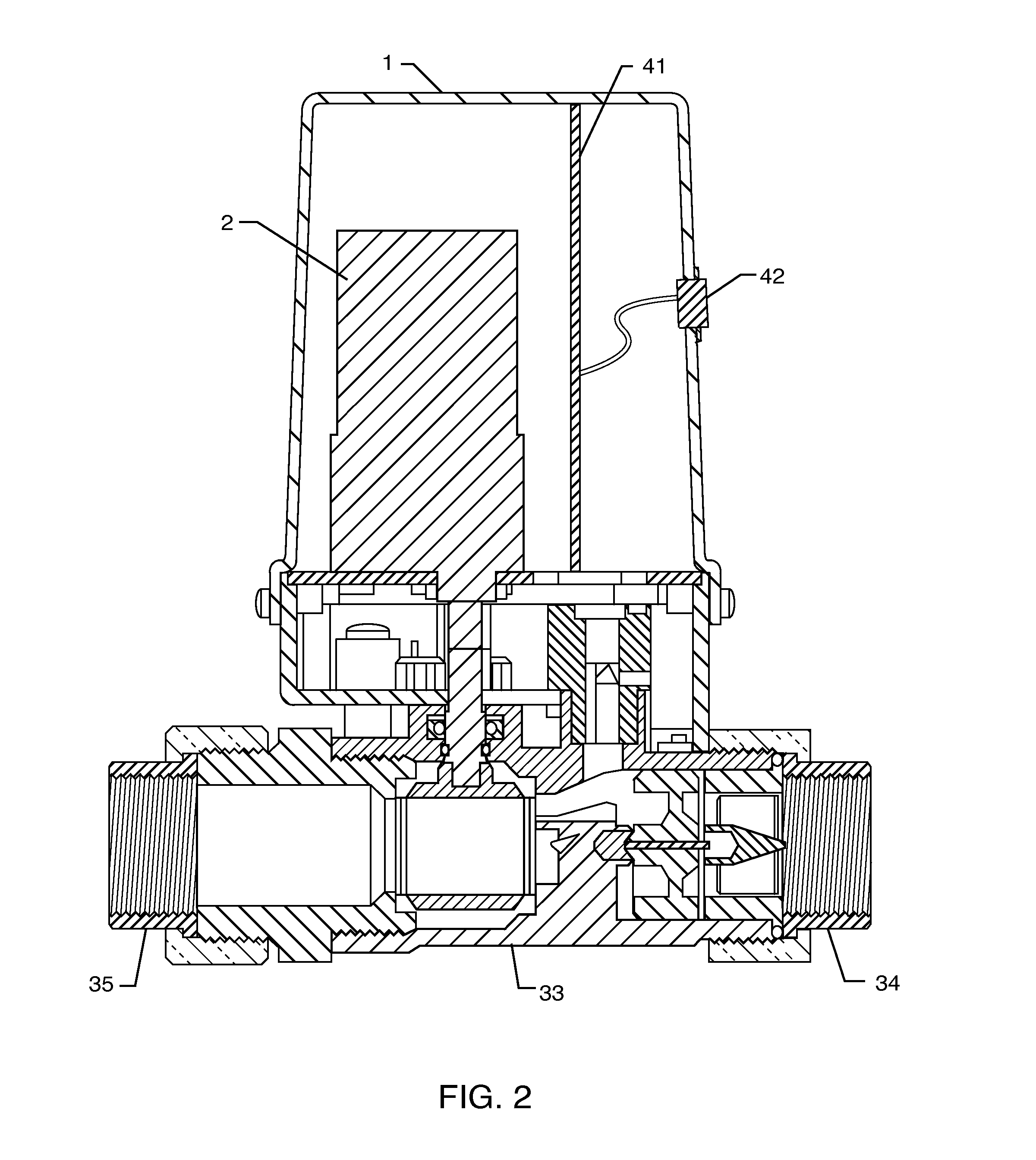
[0029]FIG. 1 is an exploded perspective view of an exemplary control device 32 embodying the present invention. Each control device 32 includes a fluid pipe section 33 including a fluid inlet 35 and a fluid outlet 34 configured to be connectable in series to a fluid pipe 36. As shown in this particular embodiment, a brass union nut 17 screws onto an adapter 20 to retain the tail piece that is in turn attached to the inlet pipe. This attachment is sealed by the union ring 18.

[0030]A fluid valve 22 is coupled in series within the fluid pipe section 33 and is housed in the valve body 24. The fluid valve 22 controls a fluid flow 37 through the fluid pipe section 33. The adapter 20 abuts an adapter o-ring 21 and captures the ball valve 22 along with the plastic balls seats 23 against the valve body 24.

[0031]The motor 2 is coupled to the ball valve 22 through the motor coupling 6 which engages a limit stop 7. The valve stem 12 engages the motor coupling 6 and also the ball valve 22. The v...


PUM


Abstract

A fluid monitoring and control system includes a central hub having a central processor, a user interface and an input/output port. A plurality of control devices communicate with the central hub. Each control device includes a fluid pipe section including a fluid inlet and a fluid outlet. A fluid valve is coupled in series within the fluid pipe section and an electric motor is mechanically connected to the fluid valve. A temperature sensor, pressure sensor and flow rate sensor are coupled to the fluid pipe section monitoring a temperature, pressure and flow rate of the fluid flow within the fluid pipe section. A control device processor is controllably connected to the electric motor, temperature sensor, pressure sensor and flow sensor. A control device input/output port is coupled to the control device processor, the control device input/output port in communication with the input/output port of the central hub.

Description

CROSS-REFERENCE TO RELATED APPLICATIONS[0001]This non-provisional application claims priority to provisional application 61 / 766,105 filed on Feb. 18, 2013, the contents of which are fully incorporated herein with this reference.FIELD OF THE INVENTION[0002]The present invention generally relates to fluid monitoring and control. More particularly, the present invention relates to a central hub that is in communication with a plurality of control devices placed at various locations to monitor and control fluids.BACKGROUND OF THE INVENTION[0003]The plumbing industry has lagged behind its related industries in development of fundamentally new and innovative technologies in recent decades. Due to the passive nature of fluids, the delivery of liquid, gas and air has hardly changed since their initial development decades ago. Improvements in the industry have traditionally been focused on product redesigns and the use of modified materials. The net effect of this stagnation has become aging...

Claims


Application Information

Patent Timeline
Patent Type & Authority Applications(United States)
IPC IPC(8): G05D7/06G05D16/20
CPCG05D16/20G05D7/0617G05D7/0635Y10T137/7761
Inventor HALIMI, HENRY M.
Owner FORTUNE BRANDS WATER INNOVATIONS LLC
Why Eureka
Try Eureka