Power tool with fluid boost

a technology of power tools and fluid boosts, applied in the field of fluid boosts, can solve the problems of increasing the cost of manufacturing, reducing the efficiency and increasing the cost of air-powered power tools. , to achieve the effect of reducing the “air hog” deficiency of conventional dual-chamber motors and enhancing the volume of pressurized air admitted

Inactive Publication Date: 2014-08-21
STANLEY WORKS THE
View PDF0 Cites 21 Cited by
  • Summary
  • Abstract
  • Description
  • Claims
  • Application Information

AI Technical Summary

Benefits of technology

[0008]It has been discovered that a dual-chamber air motor can, in fact, be used to drive a power tool by following the teachings of the present invention. By restricting the size of an air inlet to permit just enough volume of pressurized air into the motor chambers to drive the tool within an acceptable range of power, the “air hog” deficiency associated with conventional dual-chamber motors can be eliminated. In the vast majority of applications for which the power tool is used, this restricted air volume works just fine. And when the operator encounters the infrequent resistance in a workpiece that would otherwise stall the tool, the operator can actuate a two-step throttle-actuated dual ported mechanism of the present invention to admit boost air into the motor air chambers to augment the volume of pressurized air admitted into the motor. As a result, the stall is overcome and full power is delivered to the tool output member. Other benefits also result from the coactions of the dual-chamber motor and the air boost system of the present invention.

Problems solved by technology

However, the utility of an air-powered tool is often limited by the availability and size of supplies of pressurized air.
Another difficulty is that conventional air-powered power tools use single-chamber rotary air motors.
Unfortunately, this often entails employing a multi-stage transmission and other complicated gearing arrangements, which cause the tool to have a longer length, to be heavier, and to cost more to manufacture.
Again, this approach is costly, because the higher the desired supply of air pressure, the more expensive it becomes in fuel and compressor size.
And as just noted, not everyone has access to more powerful sources of pressurized air.
However, for that very reason they are also notorious “air hogs”, and they would likely quickly drain the typical small compressor tank available to homeowners and smaller contractors.
Accordingly, until now, it has not been thought practical to use a dual-chamber air motor in a power tool.

Method used


Image

  • Power tool with fluid boost
  • Power tool with fluid boost
  • Power tool with fluid boost

Examples


Embodiment Construction

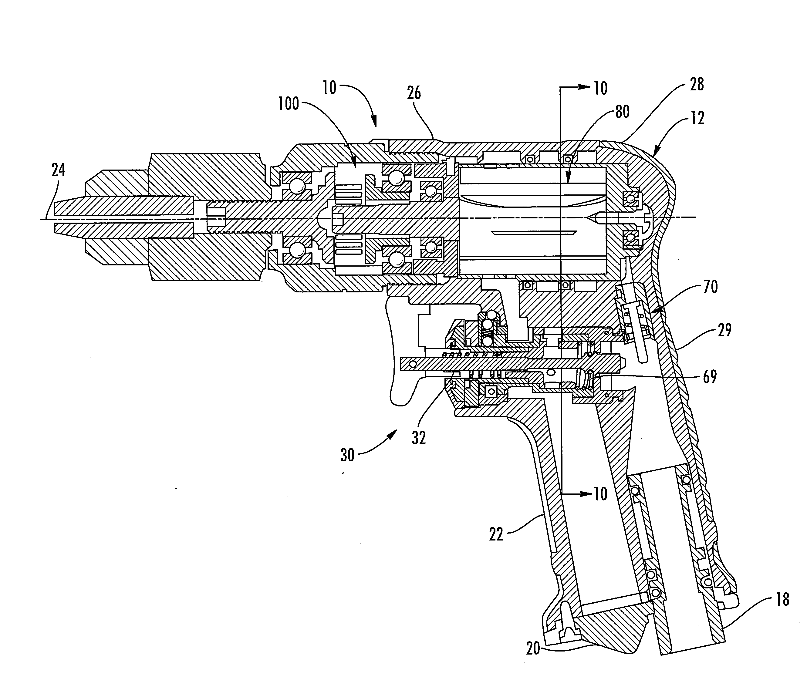
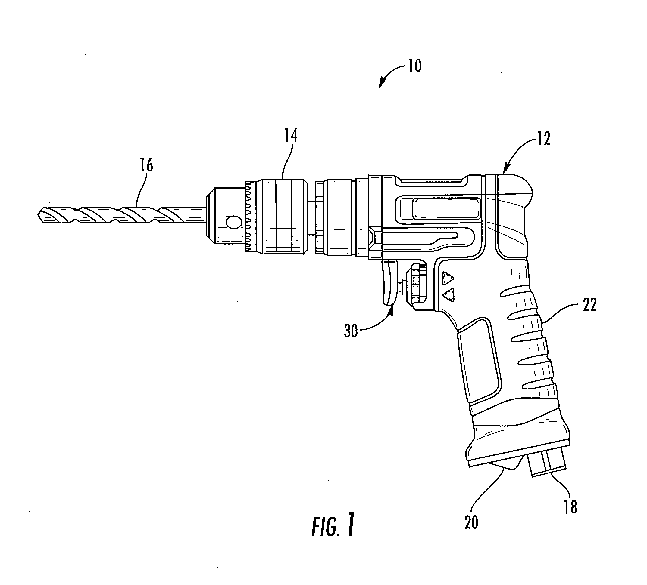
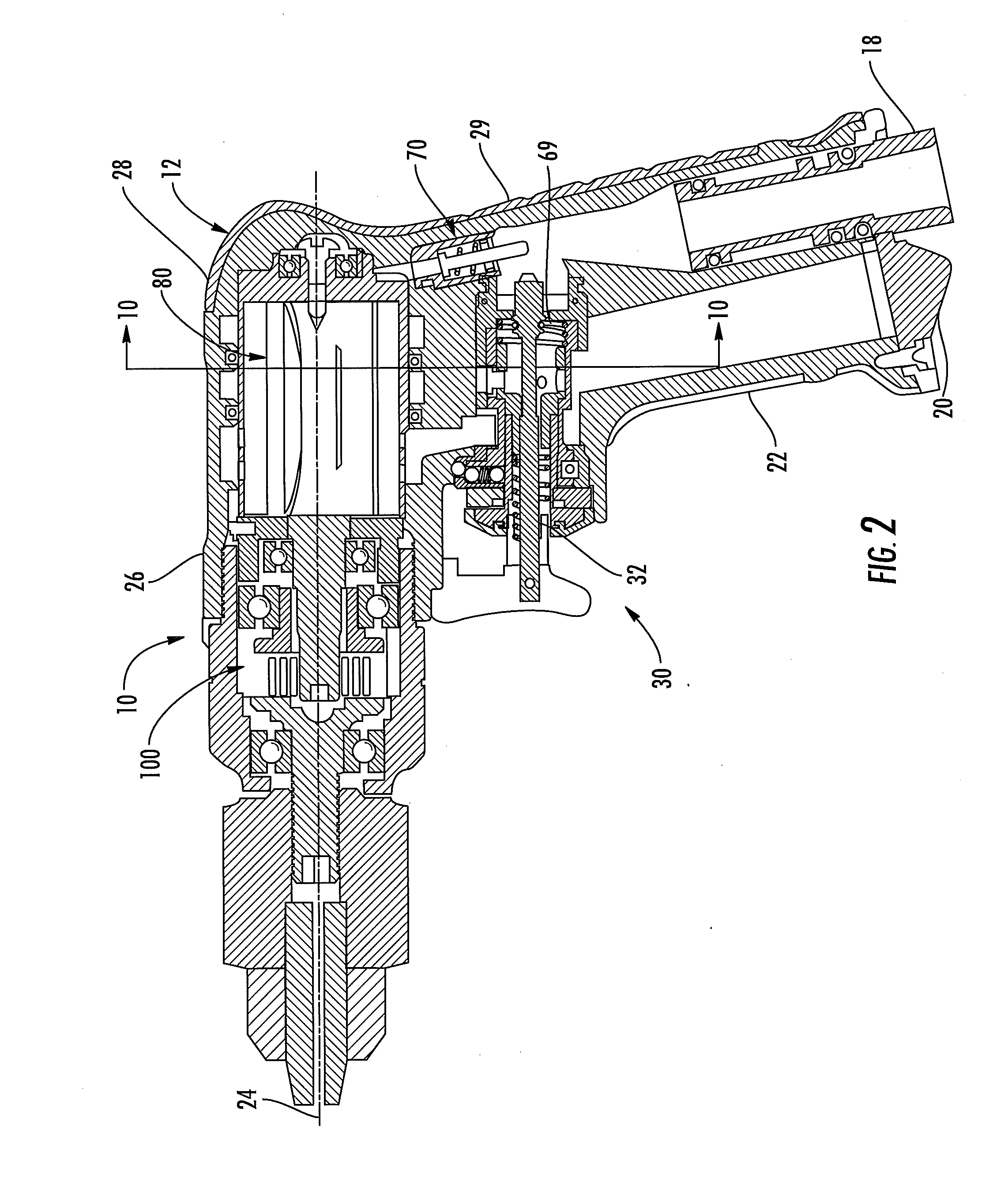
[0078]FIG. 1 shows one embodiment of a fluidically-driven power tool 10 of the present invention. Although the embodiment shown uses an air-powered motor as the prime mover to drive a drill bit, it will be appreciated that the present invention is also applicable to tools using other pressurized fluids to drive several types of prime movers to drive other types of output members. For example, it is contemplated that the concepts of the throttle system of the present invention could also be applied to such tools as hammers, having impact mechanisms driven by such prime movers as reciprocating fluid-driven piston systems using various numbers and configurations of fluid chambers.

[0079]The embodiment of the power tool 10 described in detail herein includes a housing 12, a chuck 14 driven by the power tool, to which a tool element such as a drill bit 16 is connected. The power tool 10 is connected to a source of pressurized air (not shown) by a connection 18, and exhausts air through a ...


PUM

PropertyMeasurementUnit
axial distanceaaaaaaaaaa
angleaaaaaaaaaa
speedaaaaaaaaaa

Abstract

A power tool includes a fluidically-driven prime mover controlled by a multi-stage, throttle-actuated dual-ported mechanism disposed in the power tool. When the first stage is actuated, pressurized fluid is admitted into the prime mover via a first delivery path in fluid communication with one of the ports. When the second stage is actuated, pressurized fluid is also admitted into the prime mover via a second delivery path in fluid communication with the other port to augment the volume of pressurized fluid admitted into the prime mover via the first delivery path. In one embodiment of the present invention, the prime mover includes a dual-chamber air motor. Upon detecting an imminent stall condition, an operator can axially advance a trigger stem to admit a boost of pressurized air into the motor via the second delivery path.

Description

FIELD OF THE INVENTION[0001]The present invention relates to fluidically-driven power tools, and more particularly to a power tool driven by an air motor.BACKGROUND OF THE INVENTION[0002]Fluidically-driven prime movers are used to drive a variety of output members, whether powered by air, water or other fluid. Power tools using prime movers driven by pressurized air use for example reciprocating systems for driving impact mechanisms, and rotary motors for drilling, screwdriving, sawing, and the like. However, the utility of an air-powered tool is often limited by the availability and size of supplies of pressurized air.[0003]Another difficulty is that conventional air-powered power tools use single-chamber rotary air motors. Such a power tool has a no-load output speed at the drill bit of about 23,000 rpm at about 10 inch pounds of torque. A glance at the speed / torque curve of a conventional air-driven drill will illustrate how quickly the output speed drops as torque resistance inc...

Claims


Application Information

Patent Timeline
Patent Type & Authority Applications(United States)
IPC IPC(8): B23Q5/06B25F5/00
CPCB23Q5/06B23Q2705/04B23Q2005/005B25F5/00B25F5/005Y10T29/49718
Inventor LEHNERT, MARKJARDELEZA, GUALBERTO
Owner STANLEY WORKS THE
Why Eureka
Try Eureka