

Quantum interference device, atomic oscillator, and moving object
- Summary
- Abstract
- Description
- Claims
- Application Information
AI Technical Summary
Benefits of technology
Problems solved by technology
Method used
Image

Examples
first embodiment
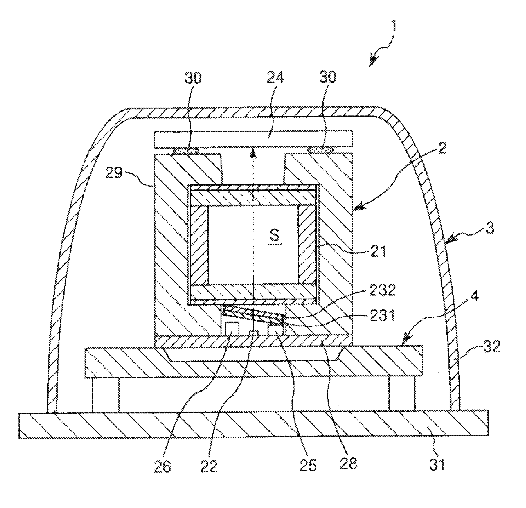
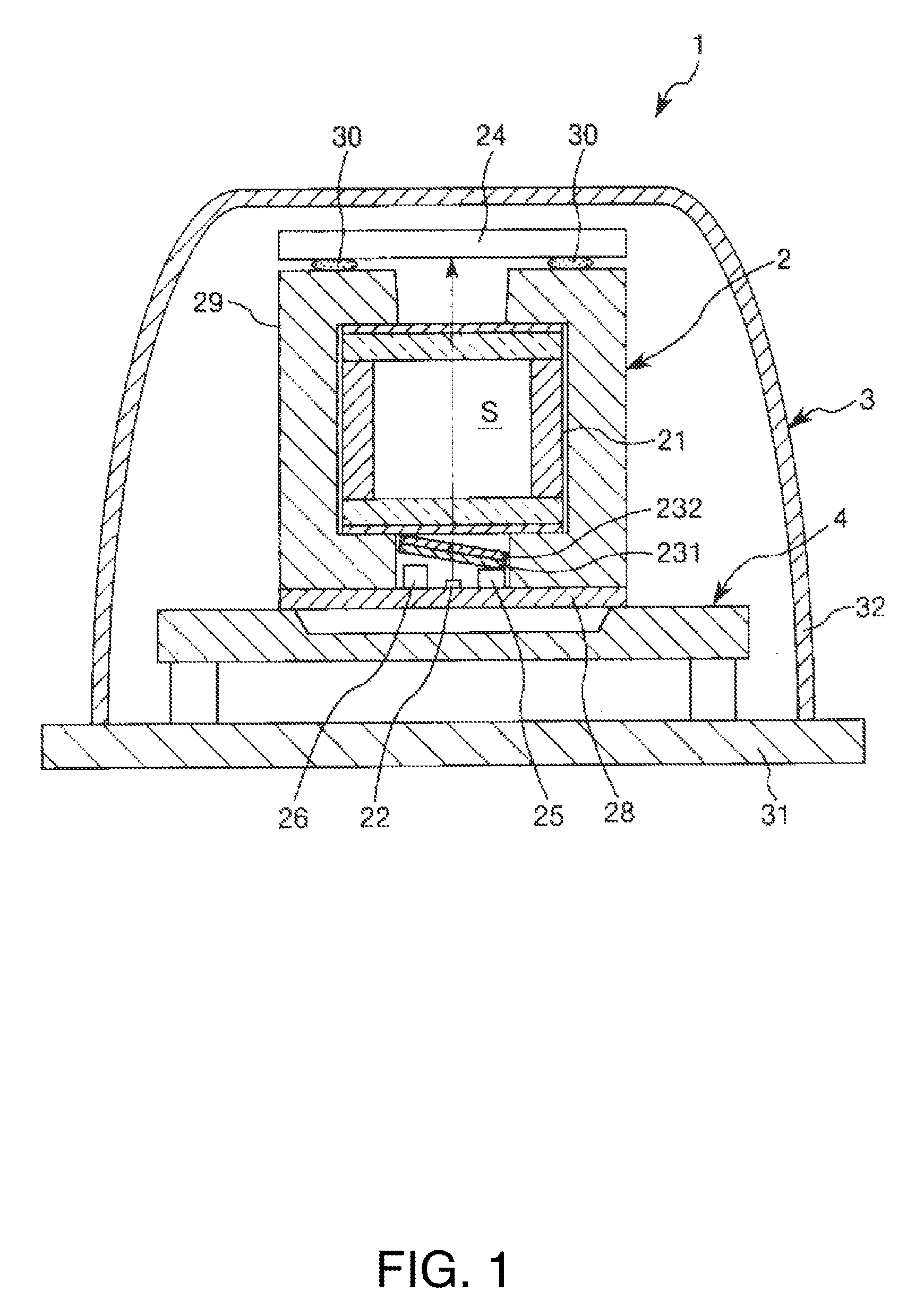
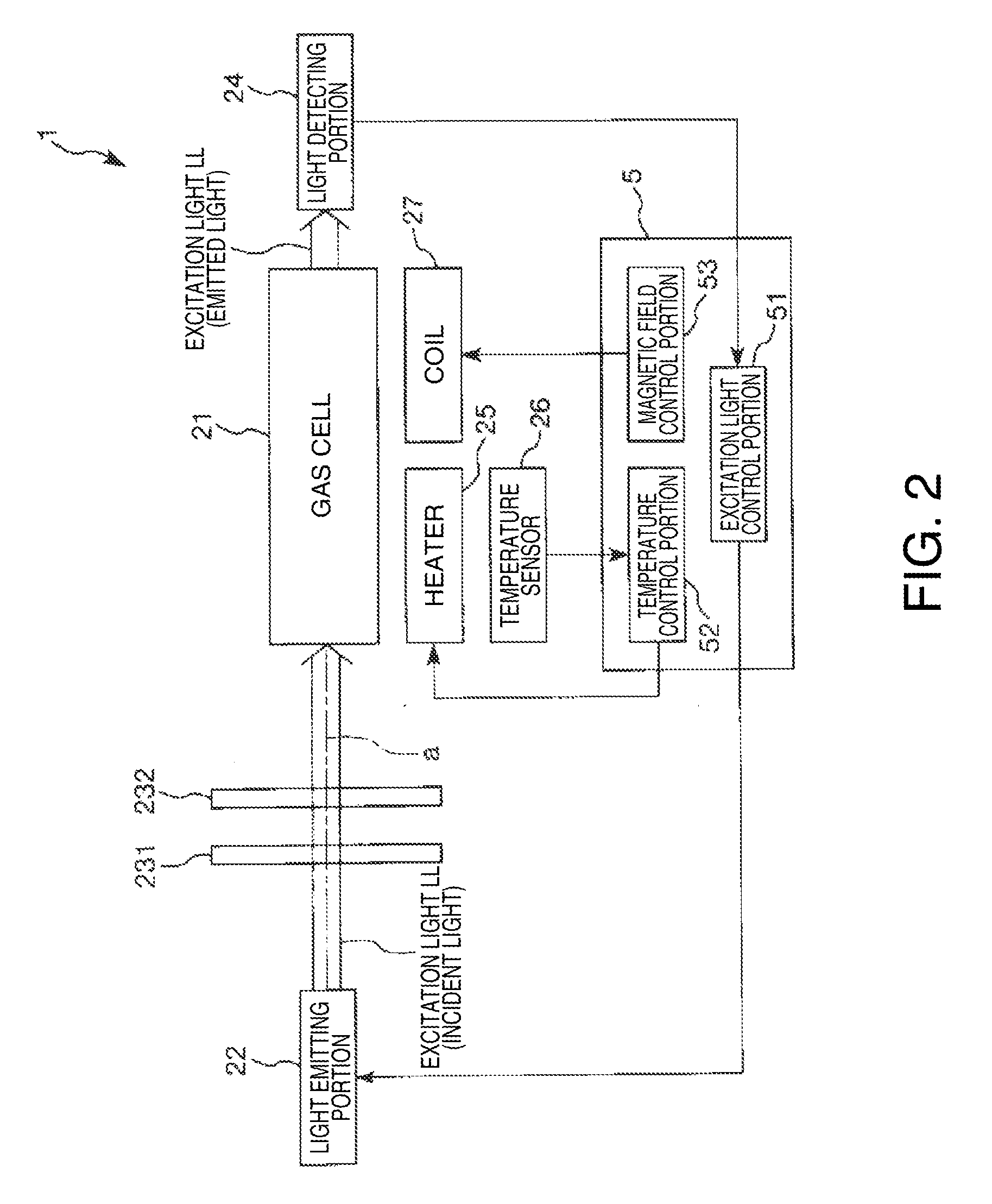
[0051]FIG. 1 is a cross-sectional view showing an atomic oscillator (quantum interference device) according to a first embodiment of the invention, and FIG. 2 is a schematic diagram of the atomic oscillator shown in FIG. 1. In addition, FIG. 3 is a diagram for explaining the energy state of alkali metal in a gas cell of the atomic oscillator shown in FIG. 1, and FIG. 4 is a graph showing the relationship between the frequency difference of two light components from a light emitting portion and the detection intensity in a light detecting portion for the light emitting portion and the light detecting portion of the atomic oscillator shown in FIG. 1. In addition, FIG. 5 is a cross-sectional view for explaining a heating portion and a connection member of the atomic oscillator shown in FIG. 1, FIG. 6 is an exploded view for explaining a gas cell and the connection member of the atomic oscillator shown in FIG. 1, and FIG. 7 is a plan view for explaining the gas cell and the connection m...
second embodiment
[0177]Next, a second embodiment of the invention will be described.
[0178]FIG. 9 is a cross-sectional view showing an atomic oscillator (quantum interference device) according to the second embodiment of the invention, FIG. 10 is a plan view of a support portion of the atomic oscillator shown in FIG. 9, and FIG. 11 is a partially enlarged perspective view of the support portion shown in FIG. 10.
[0179]The atomic oscillator according to the present embodiment is the same as the atomic oscillator according to the first embodiment described above except that the configuration of the support member and the arrangement of the light emitting portion are different.
[0180]Hereinafter, the atomic oscillator of the second embodiment will be described focusing on the differences from the above embodiment, and explanations on the same matters will be omitted. In addition, in FIGS. 9 and 10, the same reference numerals are given to the same components as in the embodiment described above.
[0181]An a...
third embodiment
[0202]Next, a third embodiment of the invention will be described.
[0203]FIG. 12 is a partially enlarged perspective view showing a support portion according to the third embodiment of the invention.
[0204]An atomic oscillator according to the present embodiment is the same as the atomic oscillator according to the second embodiment described above except that the configuration of the support member is different.
[0205]Hereinafter, the atomic oscillator of the third embodiment will be described focusing on the differences from the above embodiment, and explanations on the same matters will be omitted. In addition, in FIG. 12, the same reference numerals are given to the same components as in each embodiment described above.
[0206]The atomic oscillator of the present embodiment includes a support member 4B (support portion) instead of the support member 4A in the atomic oscillator 1A of the second embodiment described above.
[0207]As shown in FIG. 12, the support member 4B includes a plur...
PUM
 Abstract
Description
Claims
Application Information