Image sensing apparatus and method of controlling same

a technology of image sensing and image, applied in the field of image sensing apparatus, can solve the problems of reducing the processing time needed for super-resolution processing, affecting the quality of image, and affecting the appearance of artifacts and blurring, so as to reduce the processing time and suppress the occurrence of false contours

Inactive Publication Date: 2014-08-21
FUJIFILM CORP
View PDF0 Cites 17 Cited by
  • Summary
  • Abstract
  • Description
  • Claims
  • Application Information

AI Technical Summary

Benefits of technology

[0025]In another embodiment according to the first aspect of the present invention, the super-resolution processing device includes a separation device (separation means) for separating an image, which is represented by image data, into a contour component and a non-contour component; a contour-component processing device (contour-component processing means) for applying noise reduction processing and emphasis processing to the contour component into which the image is separated by the separation device; and a combining device (combining means) for combining the contour component, which has undergone noise reduction processing and emphasis processing, with the non-contour component. The processing time needed for super-resolution processing is shortened by adopting the contour component as the object of super-resolution processing. In addition, the occurrence of false contours can be suppressed.

Problems solved by technology

An electronically zoomed image has a resolution that, in general, is inferior to that of an optically zoomed image.
However, contour correction processing suited to an electronically zoomed image is applied even to image data that has not been electronically zoomed and whose resolution is satisfactory, there is the danger that, contrary to expectation, degradation of the image-quality characteristic, such as the appearance of artifacts and blurring, will occur.

Method used


Image

  • Image sensing apparatus and method of controlling same
  • Image sensing apparatus and method of controlling same
  • Image sensing apparatus and method of controlling same

Examples


first embodiment

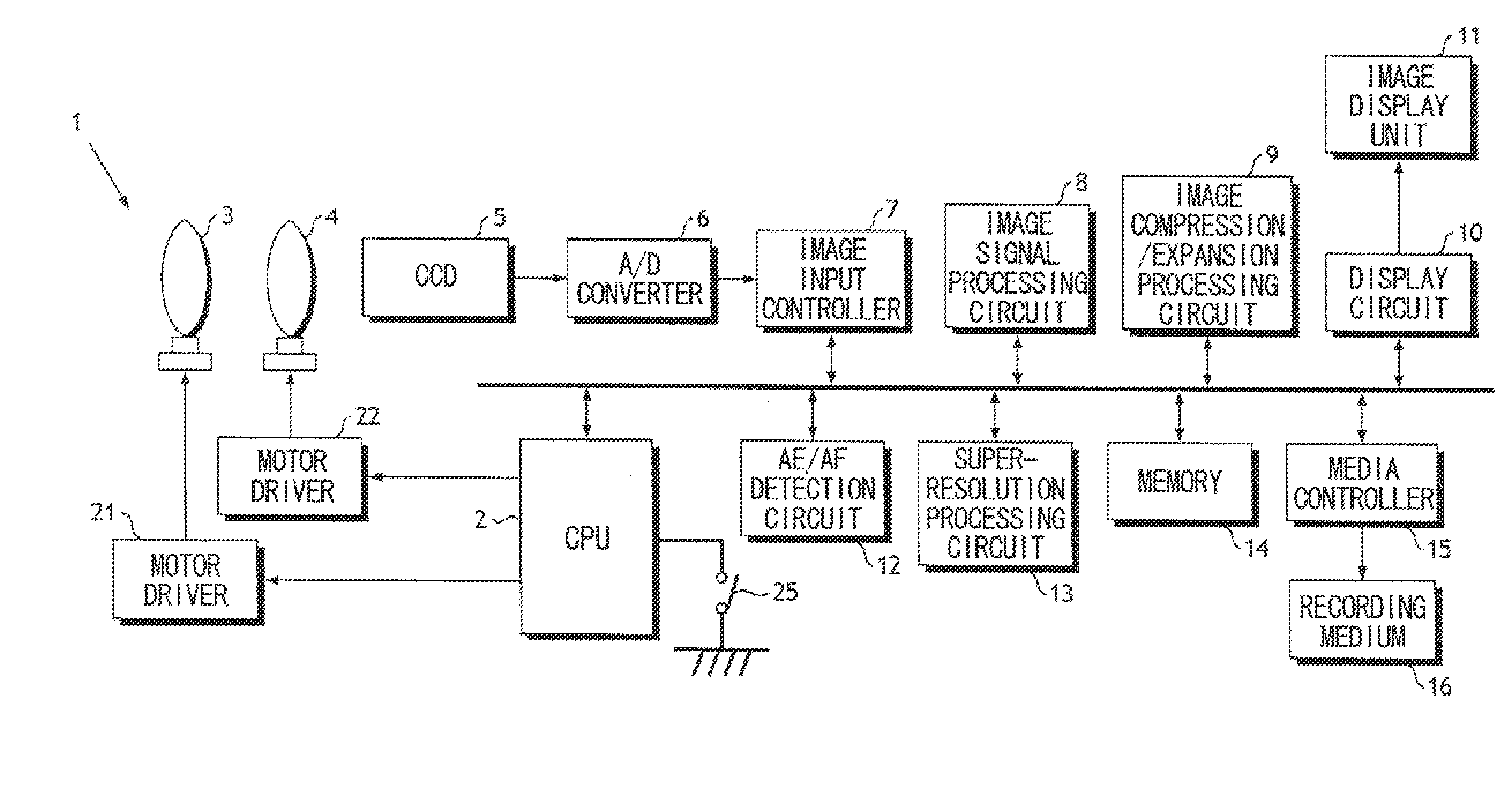
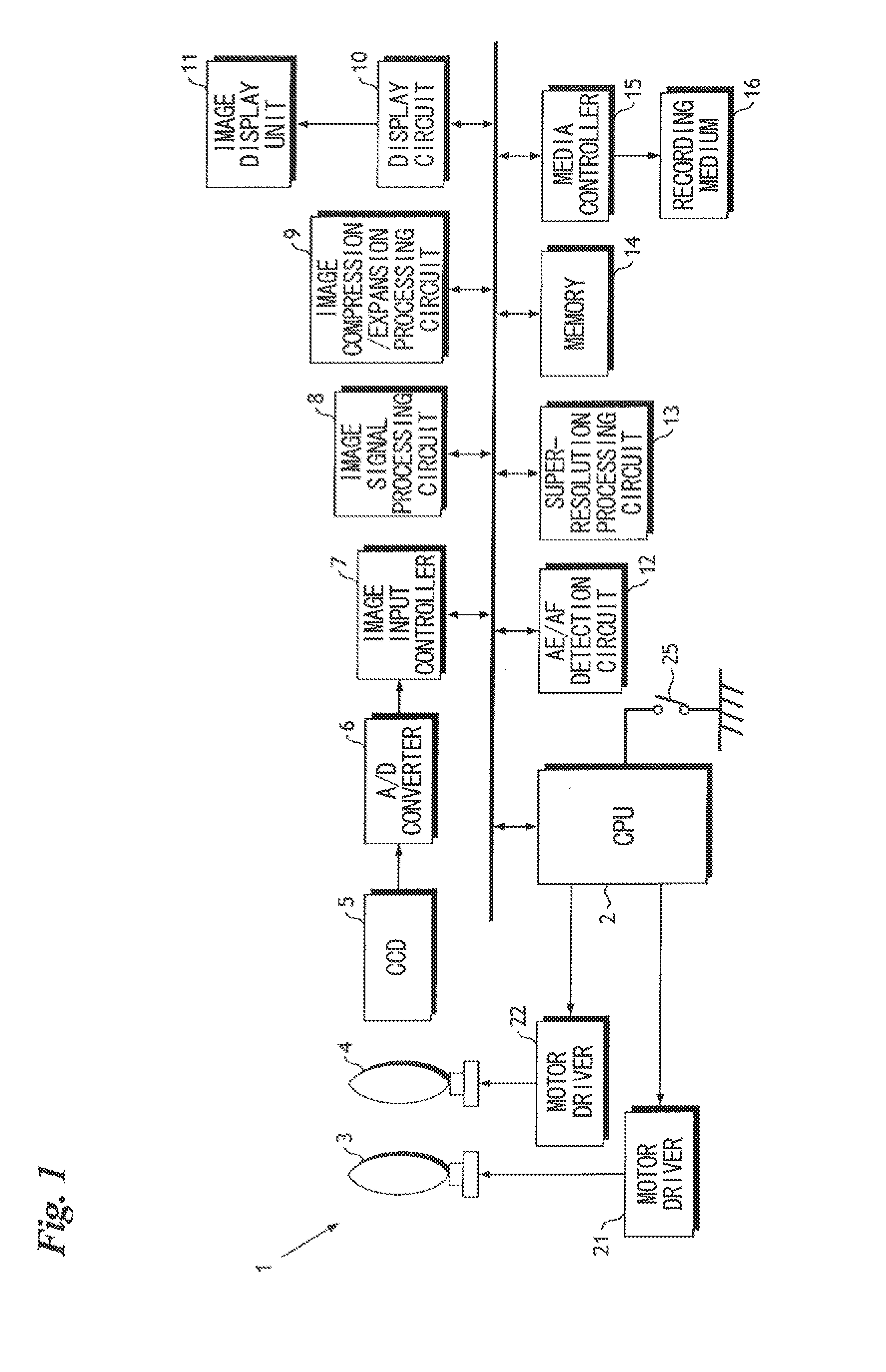
[0039]FIG. 1 is a block diagram illustrating the electrical configuration of a digital camera 1 according to a first embodiment of the present invention.

[0040]The overall operation of the digital camera 1 is controlled by a CPU 2.

[0041]A control program executed by the CPU 2, various data necessary for control, and camera settings and the like have been stored in a memory 14 (a ROM area). The memory 14 is further used as a working area of the CPU 2 and as a temporary storage area for image data (a RAM area).

[0042]An operating unit 2e includes a mode selection dial, a shutter-release button and a zoom button, etc. When an imaging mode is set by the mode selection dial included the operating unit 25, light rays representing the image of a subject impinge upon the photoreceptor surface of a CCD 5 through a zoom lens 3 and a focusing lens 4. A video signal representing the image of the subject is output from the CCD 5 at a fixed period. When the zoom button is operated to set the camera...

second embodiment

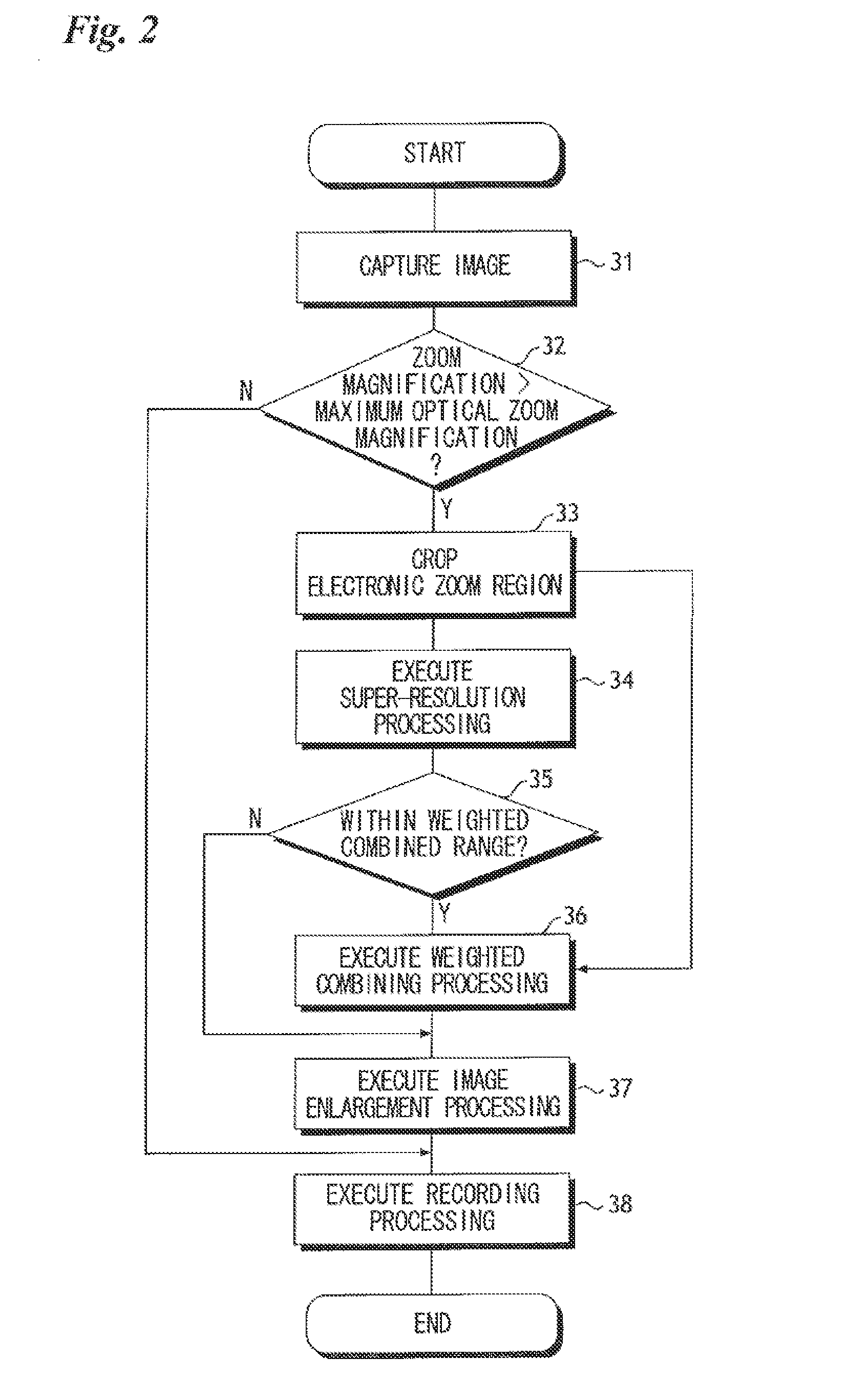
[0061]FIG. 5 is a flowchart illustrating the flow of operation of a digital camera according to a second embodiment of the present invention. Processing steps in FIG. 5 identical with those shown in the flowchart (FIG. 2) of the digital camera 1 in the first embodiment are designated by like step numbers and need not be described again. The hardware configuration of the digital camera in the second and other embodiments, described later, is the same as that of the first embodiment (FIG. 1).

[0062]The super-resolution processing executed by the super-resolution processing circuit 13 in the above-described first embodiment is applied to image data obtained by imaging. In the second embodiment, contour extraction processing is executed before super-resolution processing and only an extracted contour portion is subjected to processing by the super-resolution processing circuit 13.

[0063]With reference to FIG. 5, he cropped image is subjected to contour extraction processing (contour-compo...

third embodiment

[0067]In the first and second embodiments set forth above, the maximum optical zoom magnification Z2 which prevails when the zoom lens 3 is situated at the telephoto end (“TELE END”) is adopted as the zoom magnification (minimum zoom magnification of the weighted combining range) at which weighted combining processing is started. However, there are occasions where, even if electronic zoom processing is executed, a satisfactory resolution is maintained in a state in which the zoom magnification is low. In a third embodiment, as will be described below, instead of adopting the maximum optical zoom magnification Z2 which prevails when the zoom lens 3 is situated at the telephoto end (“TELE END”) as the zoom magnification at which weighted combining processing is started, a zoom magnification that starts weighted combining processing is decided taking spatial frequency response into consideration.

[0068]FIG. 6 is a graph illustrating the characteristic of the spatial frequency response o...


PUM


Abstract

If zoom magnification falls within an optical-zoom application scaling range of zoom magnifications Z1 to Z2, image data that has been enlarged by a zoom lens is recorded on a recording medium. If zoom magnification falls within an electronic-zoom application scaling range of zoom magnifications Z2 to Z3, the image data is subjected to super-resolution processing, super-resolution image data and image data that has not been subjected to super-resolution processing are combined by weighting processing executed such that the higher the zoom magnification, the greater the weight assigned to the super-resolution image data, and the resultant image data is subjected to electronic zoom processing and then recorded. If zoom magnification exceeds Z3, the super-resolution image data is recorded upon being subjected to electronic zoom processing.

Description

BACKGROUND OF THE INVENTION[0001]1. Field of the Invention[0002]This invention relates to an image sensing apparatus and to a method of controlling this apparatus. More particularly, the invention relates to an image sensing apparatus equipped with both an optical zoom function and an electronic zoom function, and to a method of controlling this image sensing apparatus.[0003]2. Description of the Related Art[0004]The prior art includes an apparatus which, when a zoom switch is operated, transitions from optical zoom to electronic zoom to thereby display on a display device an enlarged image the magnification of which exceeds the maximum magnification provided by optical zoom. Also known is an apparatus that displays an electronically zoomed image between optical-zoom magnifications that change in stepwise fashion (see Patent Documents 1 and 2).[0005]An electronically zoomed image has a resolution that, in general, is inferior to that of an optically zoomed image. There is also an ap...

Claims


Application Information

Patent Timeline
Patent Type & Authority Applications(United States)
IPC IPC(8): H04N5/232
CPCH04N5/23296G02B7/12H04N23/951H04N23/69
Inventor ENDO, MAIKO
Owner FUJIFILM CORP
Why Eureka
Try Eureka