Methods for analyzing and optimizing the performance of a data collection network on an electrical distribution grid

a data collection network and data collection technology, applied in powerline communication applications, transmission monitoring, instruments, etc., can solve the problem of limiting the amount of data transmitted, and achieve the effect of optimizing the performance and utility of the on-grid data collection network and maximizing the probability of their transmission

Inactive Publication Date: 2014-08-21
DOMINION ENERGY TECH +1
View PDF10 Cites 61 Cited by
  • Summary
  • Abstract
  • Description
  • Claims
  • Application Information

AI Technical Summary

Benefits of technology

[0049]In still another aspect of the invention, the Computing Platforms and the Concentrator maintain two master data tables that can be initially extracted from the utility's PNM and/or LNM, or which can be entirely accumulated from reports from the Remote Hubs. These data tables are the Inventory, which is a table of all the Remote Hubs and Subordinate Remotes that have been detected, and the Grid Map, which is a schematic representation of the grid's topology and state, similar to an LNM. The Grid Map and Inventory at substation Computing Platforms may be partial, representing only the portion of the grid accessible to the substation at least at certain times. The Grid Map and Inventory at the Concentrator generally represent the entire utility service area, although gaps in the Grid Map may exist if instrumentation of the service area with Remote Hubs and Subordinate Remotes is incomplete. When the Computing Platform at a substation receives any message from a Subordinate Remote, it compares the data in the message and the message enhancements inferred by the Substation Receiver with the data in the Inventory and Grid Map. The logic and policy on the Computing Platform are used to determine if the loc

Problems solved by technology

Encoding at lower bit rates improves reliabili

Method used


Image

  • Methods for analyzing and optimizing the performance of a data collection network on an electrical distribution grid
  • Methods for analyzing and optimizing the performance of a data collection network on an electrical distribution grid
  • Methods for analyzing and optimizing the performance of a data collection network on an electrical distribution grid

Examples


Embodiment Construction

[0075]The present invention comprises a system and methods for constructing and operating an on-grid data collection network in such a way as to integrate the network with other adjacent networks and devices present at the edge, substations, and features of an electrical distribution network, wherein the other networks and devices may include Smart Meters and the AMI and a conventional network such as the Internet. The system and methods further integrate the data collected by the on-grid data collection network at a data center and may publish the collected data to other applications. The system and methods may also employ the capabilities of the integrated networks to infer otherwise unknown static and transient attributes of the electrical distribution grid and report them via the integrated networks for the purpose of improving the physical and logical network models of the Smart Grid. This leads to the ability of the models to support Smart Grid applications such as conservatio...


PUM


Abstract

A system and methods for optimizing the performance of communication network utilizing an electrical distribution grid are disclosed. Optimization methods may include archiving historical message data and metrics from transmissions by Remote Hubs received on one or more Substation-to-Edge channels. Trends in the archived metrics over time are later analyzed to determine which combination of transmission variables such as frequency band, modulation method, drive voltage, and transmission time produce the highest message success rates overall. The results of such analysis may be used to provide feedback to the Remote Hubs or reveal necessary repairs to the network. Optimization may also be carried out locally by an individual Remote Hub by estimating the impedance of the transmission medium and adjusting either drive voltage or transmission band.

Description

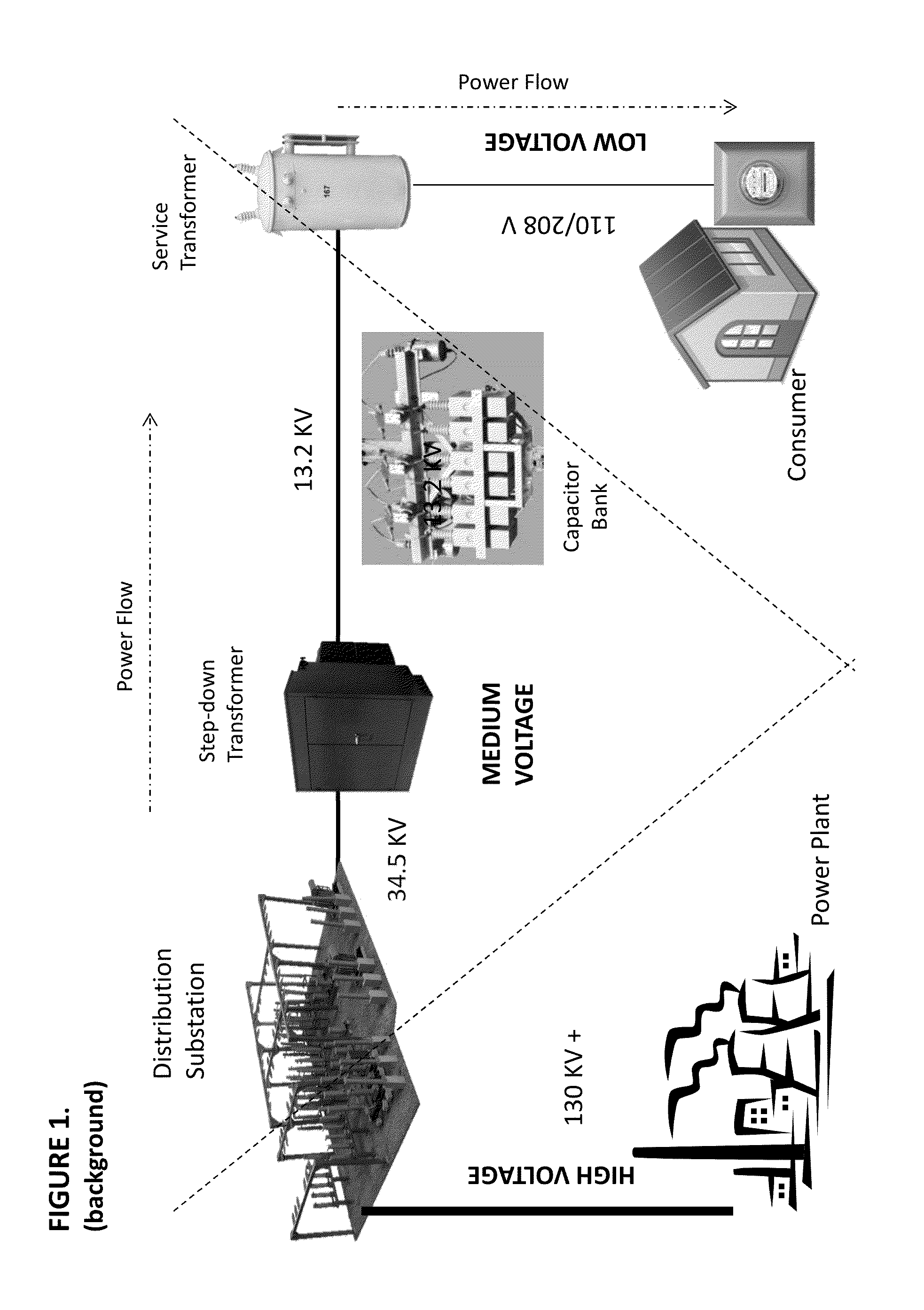
RELATED APPLICATIONS[0001]This application claims priority to U.S. Provisional Application No. 61 / 766,551, filed on Feb. 19, 2013, and U.S. Provisional Application No. 61 / 779,222, filed on Mar. 13, 2013, the contents of which are incorporated herein by reference.FIELD OF THE INVENTION[0002]The present invention is directed toward employing the electrical distribution grid as a short and long-range transmission medium and data-bearing network, and further toward the use of signals and messages on the network for the purpose of inferring schematic and topological properties of the distribution grid, which vary over time.BACKGROUND OF THE INVENTION[0003]The power grid is generally considered to be composed of two logical regions, the Transmission Grid(s) and the Distribution Grid(s). The Transmission Grid originates at large generation points such as hydroelectric dams, nuclear reactors, wind farms, and coal-fired or gas-fired power plants. Power from the generation point is transmitte...

Claims


Application Information

Patent Timeline
IPC IPC(8): H04L1/00H04B3/54
CPCH04L1/0001H04B3/54H04B2203/5466H04B2203/5433G05B13/02H04B3/546H04L41/083H04L43/0847H04L1/0009H04L1/188G06Q50/06Y04S40/121H02J13/00007H02J13/00034Y04S40/00Y02E60/00H04L41/0803Y04S10/16H04B3/542H04L41/12G01R29/18
Inventor BERNHEIM, HENRIK F.HANSELL, JERRITTMARTIN, MARCIA REID
Owner DOMINION ENERGY TECH
Why Eureka
Try Eureka