System and Method for Monitoring and Control of an Optical Modulator for an M-QAM Transmitter

a technology of optical modulator and optical modulator, applied in the field of optical communication networks, can solve the problems of increasing the amount of information that can be conveyed, and achieve the effect of reducing the disadvantages and eliminating the problems of previous systems

Active Publication Date: 2014-08-21
FUJITSU LTD
View PDF52 Cites 13 Cited by
  • Summary
  • Abstract
  • Description
  • Claims
  • Application Information

AI Technical Summary

Benefits of technology

[0003]According to embodiments of the present disclosure, disadvantages and problems associated with previous systems may be reduced or eliminated.

Problems solved by technology

Such modulation schemes may increase the amount of information that can be conveyed.

Method used


Image

  • System and Method for Monitoring and Control of an Optical Modulator for an M-QAM Transmitter
  • System and Method for Monitoring and Control of an Optical Modulator for an M-QAM Transmitter
  • System and Method for Monitoring and Control of an Optical Modulator for an M-QAM Transmitter

Examples


Embodiment Construction

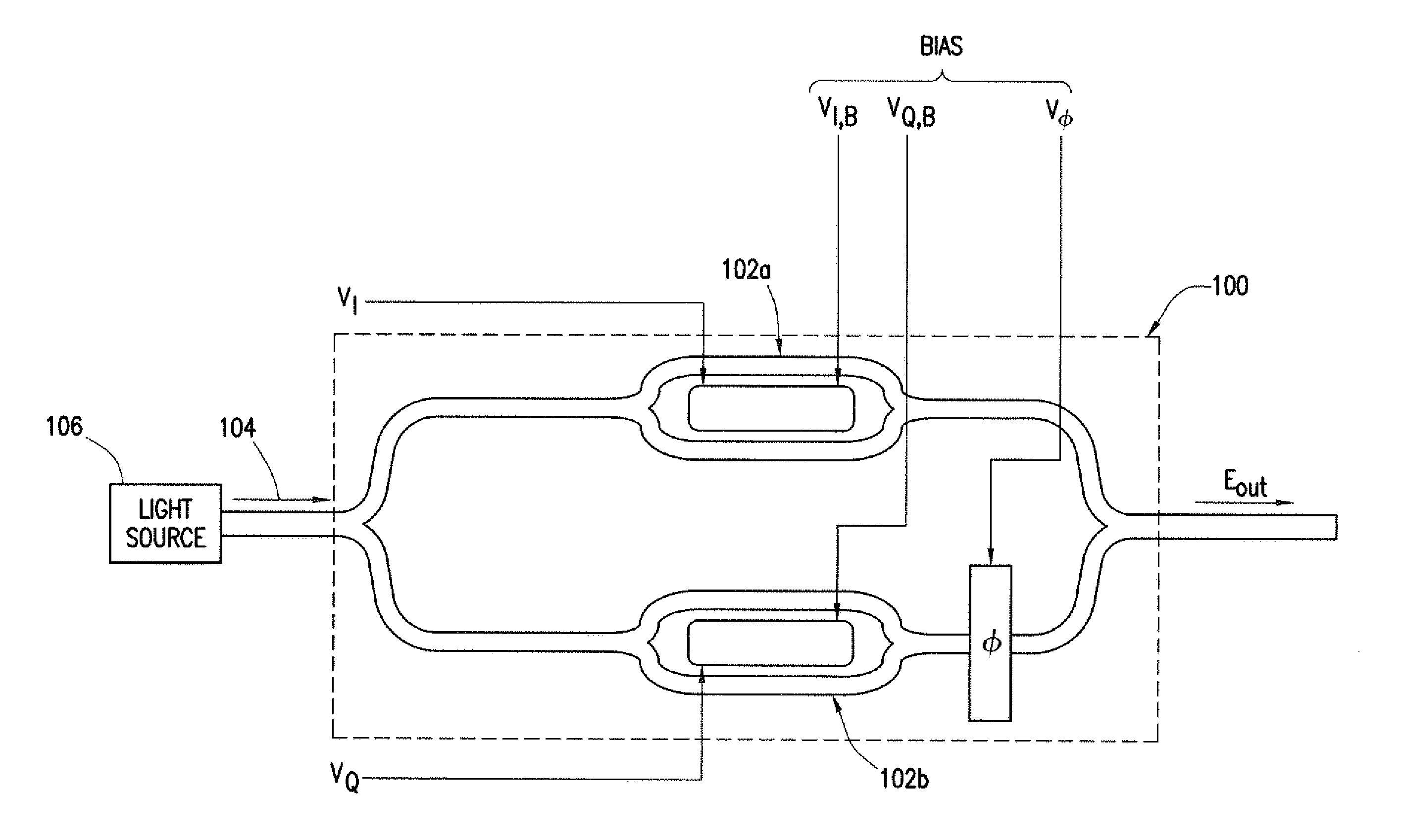
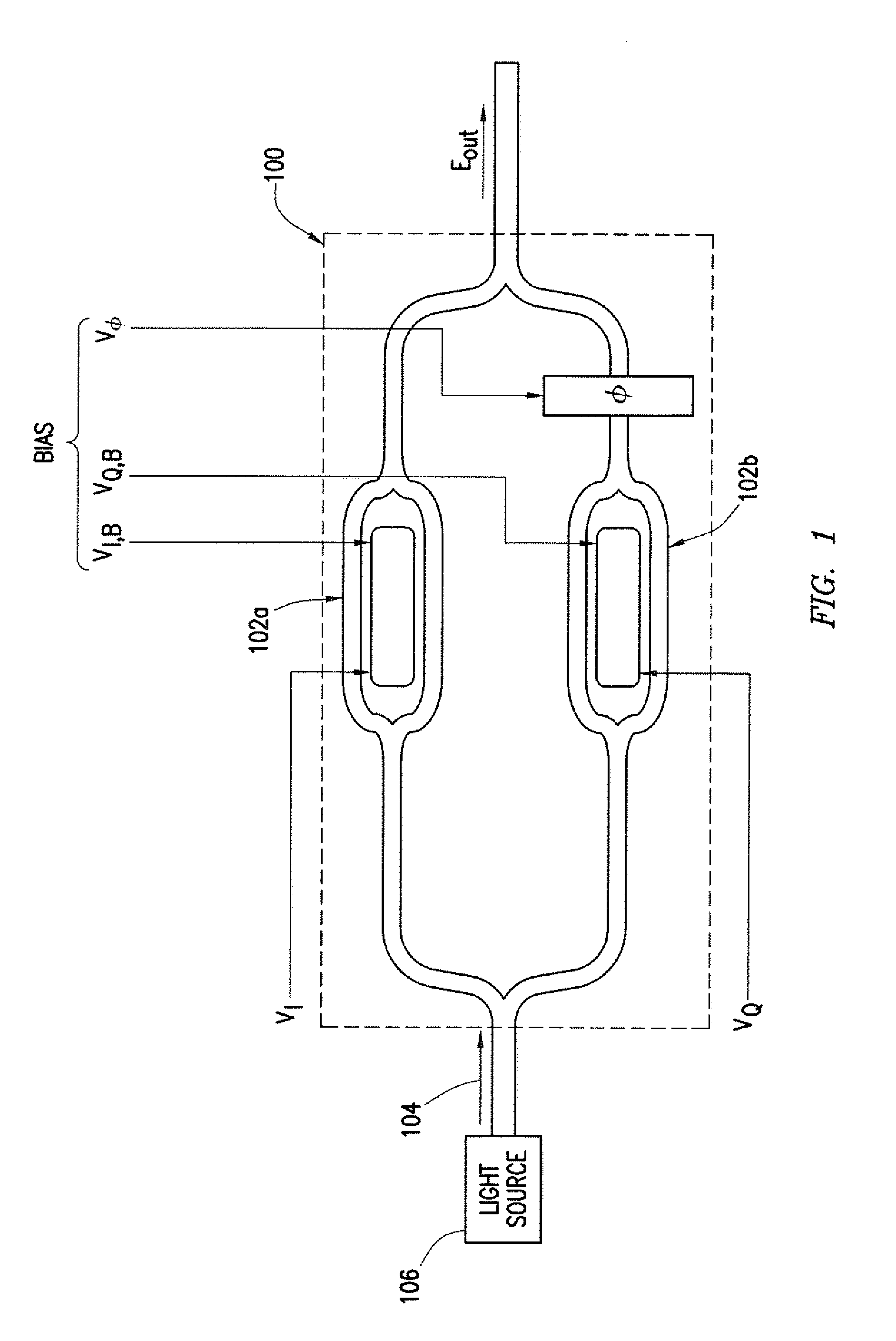
[0024]FIG. 1 illustrates an example optical IQ-modulator 100 for use in fiber-optic transmitters, according to certain embodiments of the present disclosure. Optical IQ-modulator 100 may include a set of parallel sub-modulators 102a and 102b. A light beam 104 generated by a source 106 (e.g., a continuous wave laser or any other suitable source) may be split between the two sub modulators 102 of optical IQ-modulator 100, and each sub-modulator 102 may be operable to modulate a signal onto the corresponding light beam. One arm of the split light beam 104 may be referred to as the in-phase component (I) (e.g., the portion passing through sub-modulator 102a in FIG. 1), and the other arm of the split light beam 104 may be referred to as the quadrature component (Q) (e.g., the portion passing through sub-modulator 102b in FIG. 1). The in-phase component (I) may be modulated directly by sub-modulator 102a based on an applied driving signal VI, while the quadrature component (Q) may be modu...


PUM


Abstract

A system includes an optical power meter operable to generate an optical power signal corresponding to the optical power of a received output signal generated by an optical IQ-modulator. The system further includes a processor operable to receive the optical power signal and determine, based on a minimization algorithm and the received optical power signal, a first bias voltage to be applied to a first sub-modulator of the optical IQ-modulator and a second bias voltage to be applied to a second sub-modulator of the optical IQ-modulator. The system may also include a peak power meter operable to generate a peak power signal corresponding to the peak power of the received output signal generated by the optical IQ-modulator, wherein the processor is further operable to determine, based on a minimization algorithm and the received peak power signal, a third bias voltage to be applied to a phase shift component of the optical IQ-modulator.

Description

TECHNICAL FIELD OF THE INVENTION[0001]This disclosure relates generally to optical communication networks and more particularly to a system and method for monitoring and control of an optical modulator for an M-QAM transmitter.BACKGROUND OF THE INVENTION[0002]Telecommunications systems, cable television systems and data communication networks may use optical networks to rapidly convey large amounts of information between remote points. In an optical network, information may be conveyed in the form of optical signals through optical fibers. Optical fibers may comprise thin strands of glass capable of communicating the signals over long distances with very low loss. Optical networks often employ modulation schemes to convey information in the optical signals over the optical fibers. Such modulation schemes may increase the amount of information that can be conveyed. For example, in quadrature amplitude modulation (QAM), the information carried by the optical signal may be conveyed by ...

Claims


Application Information

Patent Timeline
Patent Type & Authority Applications(United States)
IPC IPC(8): H04B10/516
CPCH04B10/516H04B10/5053H04B10/50575H04B10/541
Inventor KIM, INWOONGVASSILIEVA, OLGAPALACHARLA, PAPARAOSEKIYA, MOTOYOSHI
Owner FUJITSU LTD
Why Eureka
Try Eureka